Study the given circuit diagram and complete the table given below: Switch 9 6 4 4 7 Name the devices given in the cir 9 ooooooo Secondary circuit Primary circuit Number of the device voltmeter secondary ammeter primary 3 Input AC source 00000 ammeter secondary transformer load resistor voltmeter primary 46 1 8 3
Study the given circuit diagram and complete the table given below: Switch 9 6 4 4 7 Name the devices given in the cir 9 ooooooo Secondary circuit Primary circuit Number of the device voltmeter secondary ammeter primary 3 Input AC source 00000 ammeter secondary transformer load resistor voltmeter primary 46 1 8 3

Classical Dynamics of Particles and Systems
5th Edition
ISBN:9780534408961
Author:Stephen T. Thornton, Jerry B. Marion
Publisher:Stephen T. Thornton, Jerry B. Marion
Chapter13: Continuous Systems; Waves
Section: Chapter Questions
Problem 13.14P

Related questions
Question
![Table - Measured Values
Input voltage Input Current Output Voltage Output current
Vp [V]
Ip [A]
Vs [V]
Is [A]
5.28
0.046
1.119
0.08
Answer the following:
QUESTION - 1
Study the given circuit diagram and complete the table given below:
3
Name the devices given in the
cir
Secondary circuit
Primary circuit
Number of the device voltmeter secondary
ammeter primary
3
Input AC source
ammeter secondary
6
transformer
load resistor
4
voltmeter primary
9
Switch
ell](/v2/_next/image?url=https%3A%2F%2Fcontent.bartleby.com%2Fqna-images%2Fquestion%2Fffea5e52-5925-4877-9eae-06296cd6f34b%2Fa3375003-e1ef-4276-9f0c-98025c444a35%2Fnubxnv_processed.png&w=3840&q=75)
Transcribed Image Text:Table - Measured Values
Input voltage Input Current Output Voltage Output current
Vp [V]
Ip [A]
Vs [V]
Is [A]
5.28
0.046
1.119
0.08
Answer the following:
QUESTION - 1
Study the given circuit diagram and complete the table given below:
3
Name the devices given in the
cir
Secondary circuit
Primary circuit
Number of the device voltmeter secondary
ammeter primary
3
Input AC source
ammeter secondary
6
transformer
load resistor
4
voltmeter primary
9
Switch
ell
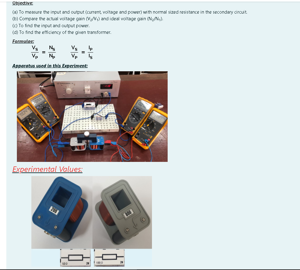
Transcribed Image Text:Objective:
(a) To measure the input and output (current, voltage and power) with normal sized resistance in the secondary circuit.
(b) Compare the actual voltage gain (V2/V,) and ideal voltage gain (N2/N,).
(c) To find the input and output power.
(d) To find the efficiency of the given transformer.
Formulae:
Vs
Ns
Vs
Ip
Vp
Np
Vp
Is
Apparatus used in this Experiment:
OSS
0624
Experimental Values:
200
800
100
100 0
Expert Solution
This question has been solved!
Explore an expertly crafted, step-by-step solution for a thorough understanding of key concepts.

Step by step
Solved in 6 steps with 1 images

Knowledge Booster


Learn more about
Need a deep-dive on the concept behind this application? Look no further. Learn more about this topic, physics and related others by exploring similar questions and additional content below.Recommended textbooks for you
Classical Dynamics of Particles and Systems
Physics
ISBN:
9780534408961
Author:
Stephen T. Thornton, Jerry B. Marion
Publisher:
Cengage Learning

Glencoe Physics: Principles and Problems, Student…
Physics
ISBN:
9780078807213
Author:
Paul W. Zitzewitz
Publisher:
Glencoe/McGraw-Hill

Classical Dynamics of Particles and Systems
Physics
ISBN:
9780534408961
Author:
Stephen T. Thornton, Jerry B. Marion
Publisher:
Cengage Learning
Glencoe Physics: Principles and Problems, Student…
Physics
ISBN:
9780078807213
Author:
Paul W. Zitzewitz
Publisher:
Glencoe/McGraw-Hill