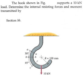
supports a 10-kN load. Determine the internal resisting forces and moment The hook shown in Fig. transmitted by Section bb. 30 b b kR= 100 mm 10 kN


Q: Solve Prob. 4.133, assuming that cable GBH is replaced by a cable GB attached at G and B.(Reference…
A: The free body diagram for the frame ACD is given below,
Q: Q1. The steel rod AC and brass rod CD are rigidly joined at C. The loads acting are P=60 kN and Q=80…
A:
Q: The horizontal beam is assumed to be rigid and supports the distributed load shown. Determine the…
A:
Q: Problem 1: a) Draw the free body diagram of the member ABC? b) Determine the reaction forces at the…
A:
Q: A steel bar has three axial loads applied as shown in Fig. Determine the axial forces transmitted by…
A: The free body explains how the loading acts
Q: A semicircular rod is loaded as shown. Determine the internal forces at point J.
A: The free-body diagram of the section will be given as follows,
Q: A polystyrene rod consisting of two cylindrical portions AB and BC is restrained at both ends and…
A:
Q: Solve Prob. 3.116, assuming that P= 60 N.(Reference to Problem 3.116):A machine component is…
A: Given data: *The force P is assumed as zero. *The distance of the force 80 N and P from G is dC=640…
Q: 4 kN A frame composed of three members linked together by hinges. This tire is subject to the…
A:
Q: II. A rope is looped over the two fixed posts each of 16 cm diameter as shown, If u= determine the…
A:
Q: 2.5 m The jib crane is pin connected at ( A ) and supported by a smooth collar at ( B ). determine…
A:
Q: 24. The rigid pipe BC shown is supported by a pin at C and an A- 36 guy wire AB (E = 200 GPa). The…
A:
Q: The ABD bracket is supported by a pin at A and the cable DE. Determine the internal forces…
A: Given: Length of BC=180 mm=0.18 m Because angle between the BD and AD: →θ=tan-1300+100300=53.13°…
Q: 2) Reqd: Determine e of A relative to D G = 12 x 10° psi MN Ib t U-41 0001 1000 lb ft 900 lb ft er…
A:
Q: A beam is subjected to a linearly distributed downward load and rests on two wide supports BC and DE…
A: Given Data: The beam is subjected to 3 distributed loads. One is a trapezoidal load and the other…
Q: A three-bar frame is loaded and supported as Determine the internal resisting forces shown in Fig.…
A: The free body diagram for the bar ABC is given below, The expression for the angle θ, On taking…
Q: Two solid cylindrical rods support a load of P = 22 kN as shown. Determine the axial load in rod…
A:
Q: A 1-in.-square aluminum strut is maintained in the position shown by a pin support at A and by sets…
A: The moment of inertia is written as, If the length AB is considered, the one end is hinged and the…
Q: A power transmission cable consists of ten copper wires each of 1.5 mm diameter surrounding three…
A:
Q: :A cantilever of 7 m length carries a uniformly distributed load of 4 KN/m over a length of 4 m from…
A: The Shear Force Diagram (SFD) and the Bending Moment Diagram (BMD) are very important for analyzing…
Q: Show that for a plane curve the torsion T = 0.
A: To prove, T→=dr→ds=dx/dsdy/dso
Q: Which of the following most nearly gives the maximum uniform loading "w" in N/m that the cable can…
A: According to Bartleby guidelines, we are allowed to solve only a single problem.Please post the rest…
Q: A vibration isolation unit consists of two blocks of hard rubber bonded to a plate AB as shown. A…
A:
Q: The load F on the rigid body shown below is supported by roller support at B and fixed support at A.…
A:
Q: 500mm 500mm 13. For the frame and loading shown, determine the components of all forces acting on…
A: The free body diagram for the frame is given below,
Q: A T-shaped bracket supports the four loads shown. Determine the reactions at A and B if a = 12cm.…
A:
Q: Activity 1. For the truss shown in the figure, determine the forces acting on members AB, AC,BC,CE…
A: Given, The lengths, AC=1.5 mAE=1.5 mAG=4.5 mAH=6 mDE=2 m
Q: 2. Determine the cross-sectional areas of members AG, BC, and CE for the truss shown. The stresses…
A:
Q: Homework8: A steel shaft of two segments AB and BC which arc rigidly fastened at B Determine: 1)…
A:
Q: Determine the magnitude of the pin reactions at Band Cif W = 1720 Ib. 3.7' 3.7' BI 2.0' Answers: B =…
A:
Q: A bar is loaded and supported as shown in Fig. Determine the axial forces transmitted by transverse…
A:
Q: Knowing that the central portion of the link BD has dimensions 3mm x 30 mm made of steel with…
A:
Q: 1.5 m 3 m 400 N 200 N 1 m Member AB is supported by a cable BC and at A by a square rod which fits…
A: Given data: F1=200 NF2=400 NuBC=-0.857i+0.429j+0.286k Need to determine the tension in the cable.
Q: Determine the length L of cable which will allow a sag-to-span ratio of 1/14 for the configuration…
A: Given data: n=114d=1960 m Need to determine the length of the cable.
Q: .. M 30 IE
A: as ∑ MJ=0P X 3b = FAL X 3a⇒ FAL= 12 X 21.5= 16 kN (Tension)∑Fx=0 ⇒ FNL X Cos 30°…
Q: Question 7: Determine the ultimate moment of resistance M, of the section shown if fau = 25 N/mm'…
A:
Q: The uniform brass bar AB has a rectangular cross section and is supported by pins and brackets as…
A: Given Data Load, P= 1.8 kips, Length of the bar AB, L = 7ft=84 in Depth of the beam, d=1.5in…
Q: Four sets of flexible cables, spaced at 120° intervals, are used to stabilize a 400-ft…
A: Draw the free body diagram of the section containing point A: The axial force transmitted through…
Q: Current Attempt in Progress Determine the length L of cable which will allow a sag-to-span ratio of…
A: Sag to span ratio = n = 1/14 Cable span length = d = 1960 m Sag length = f = n.d f = (1/14) x 1960 f…
Q: CASTIGLIANO’s THEOREM.For the rigid frame shown, determine the horizontal displacement of joint E.…
A: FREE BODY Diagram
Q: NA 19.The end A of a uniform rod AB of weight W and of length a is hinged freely to a vertical wall.…
A:
Q: A three-bar frame is loaded and supported as Determine the internal resisting forces shown in Fig.…
A: Draw the F.B.D of the member ABC and BD of the frame.
Q: 6. If the frame shown is loaded by a clockwise couple of magnitude 36 N-m at B, the magnitude of the…
A: Given: The couple moment at B, M = 36 kN.m
Q: 6) Determine the reactions at A and B for the steel bar and loading shown in Fig. I, assuming a…
A: given; lets take reaction force at A=RAlets take reaction force at B=RBAC=300mmCB=300mmarea in…
Q: The pin at O can support a maximum force of 3.5 kN. What is the corresponding maximum load L which…
A: For the given mechanical system Max. support Reaction at O = 3.5 kN Let the support reaction…
Q: Determine the shortening of point B with respect to the ground at D. Segment BC weighs 1.8 kN/m and…
A:
Q: 32. Load on member BD A. 0 B. 2.05 KN (T) C. 2.05 KN (C) O D. 3.06kN (T) 33. Load on member DC A.…
A:
Q: Determine reactions in A and tension in cable as shown in figure? 300 KN 30 kN/m 20 kN/m um \l\\ B A…
A:
Q: The truss shown below is supported by a roller at A and a hinge at B and carries loads at the points…
A: At roller support, there will be only one reaction i.e., Ay(vertically upward) and Ax=0. At hinged…
Q: For the frame and loading shown, determine the internal forces at the point indicated:Point K
A:


Trending now
This is a popular solution!

Step by step
Solved in 2 steps with 4 images

- The ABD bracket is supported by a pin at A and the cable DE. Determine the internal forces immediately to the left of the load.Template: (On CD) F= 270 N; M=43.2 N.m; V = 90 NA cantilever of 5 m length carries a uniformly distributed load of 4 kN/m over a length of 3 m from the fixed end, and a point load of 4 KN at the free end. draw S.F and B.M. diagrams of the cantileverThe three-bar truss in Fig. a is subjected to a horizontal force of 5 kip. If the cross-sectional area of each member is 0.20 in2, determine the horizontal displacement at point B. E = 29(103) ksi.
- determine the factor of safety ‘n’ at point BCASTIGLIANO’s THEOREM.For the rigid frame shown, determine the horizontal displacement of joint E. EI is constant.The lever AB shown in the figure is attached to the horizontal axis BC that passes through the bearing and is welded onto the fixed bearing at C. The constant of torsion of the spring of the axis BC is K; that is, a couple of magnitude K is required to rotate r radián to end B of the shaft. If the shaft is known not to be twisted when the lever AB is horizontal, determine the value of θ corresponding to the position of equilibrium if P = 150N, l= 325 mm and K = 13,5 Nm/rad. Solve by potential energy methodology and determine the stability of the equilibrium position.
- The bar AC is supported by a joint at A and a pin B that is free to slide in the same direction (alpha) of the bar. A bar is connected at C and a force is applied in the theta direction. Consider that L1 = 2.7 m, L2 = 1.7 m, alpha = 13 °, theta = 25 °, and P = 68 kN. Determine the magnitude of the force (kN) on pin B.Static Problem. Indications:The system shown is composed of an ABG bar, supported by a pin at point A and by a collarsmooth at point B (the collar slides on the bar ABG). The collar is pinned to the BDE bar, and theRod BDE is supported by a pin at D and a cable at end E.Based on the above, determine:a) The load P, such that the cable force EF is T.b) The internal loads in a section passing through point G (normal and shear force, and momentflexing).c) Draw bar BDE horizontally and generate the shear force and moment diagramsflexing Indicate the maximum values of shear force and bending moment and their location.?= 22 lb ? = 7 in ? = 6 inA flange coupling having 180 mm bolt circle and 19 mm thick uses 12 bolts, 16 mm diameter to connect two shafts. It is used to transmit 80 Hp at 180 rpm. Determine the factor of safety in bearing if yield point in compression is 65 ksi.
- Before the load is placed on the rigid plate, the top of the central spring is 20 mm lower than the outer springs. Each outer spring is made of 24 turns of 15-mm diameter wire on a mean radius of 60 mm. The central spring consists of 16 turns of 20 mm dimeter wire on a mean radius of 80 mm. If a load P = 5 kN is now placed on the rigid plate. Disregarding the weight of the plate, use G = 83 GPa and use Light spring formula. Determine the maximum shearing stress of the in uter spring. In MPaA.The bar of negligible weight is supported by two springs, each having a stiffness k = 98 N/m. If the springs are originally unstretched, and the force is vertical as shown, determine the angle the bar makes with the horizontal, when the 31-N force is applied to the bar. B.Determine the stiffness k of each spring so that the 32-N force causes the bar to tip = 13.6° when the force is applied. Originally the bar is horizontal and the springs are unstretched. Neglect the weight of the bar.How much work is done by the force in the spring when the slender rod rotates clockwise about the fixed pin support at O from the vertical position (where AB is horizontal) to the horizontal position? The spring has a stiffness of k = 125 N/m and an unstretched length of 0.15 m. Take d1= 0.29 m and d2= 0.85 m. Choose the correct answer. a) 94.9 Joule b) 99.9 Joule c) -99.9 Joule d) 0 Joule e) -94.9 Joule