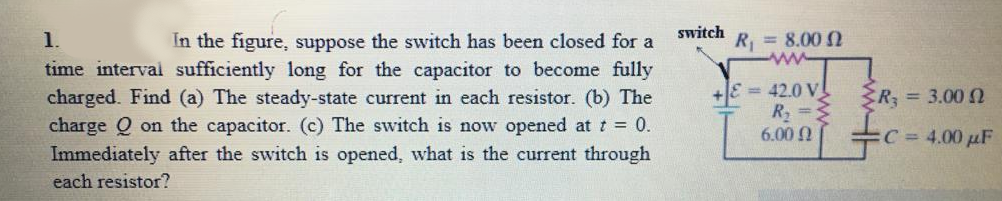
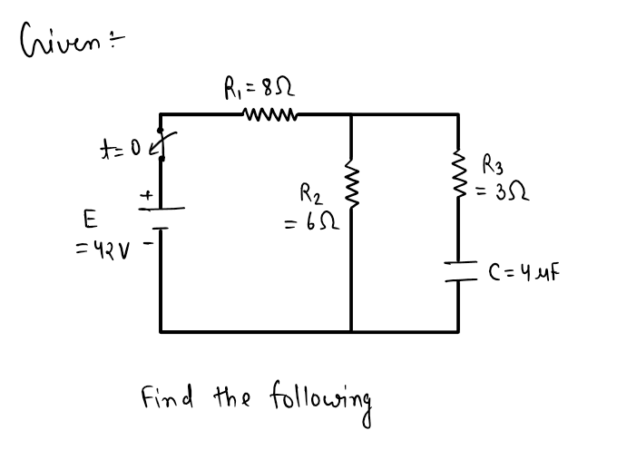
switch 1. In the figure, suppose the switch has been closed for a R = 8.00 N time interval sufficiently long for the capacitor to become fully charged. Find (a) The steady-state current in each resistor. (b) The charge Q on the capacitor. (c) The switch is now opened at t = 0. Immediately after the switch is opened, what is the current through = 42.0 V R2 6.00 Q R; = 3.00 2 C 4.00 µF each resistor?
Q: Calculate the radiation resistance of current element whose overall length is λ/50.
A: The overall length of a current element is given as le=λ50. The radiation resistance of the current…
Q: In the cross-section shown in the figure, two long straight wires held against a plastic cylinder of…
A: Given: Radius 20 cm current carried by wire 1 is 60 mA Magnitude of wire2 is 80 nT Find Angle θ2
Q: You construct an L-C circuit that contains a 30.0 mH inductor and a 655 mF capacitor. At t = 0 the…
A: Given data, Inductance L=30 μH or 30×10-6 H Capacitance C=655 μF or 655×10-6 F Charge q=0.4 mC
Q: give a description of this wave form, from a non-synchronous buck converter. The wave form is from…
A: The signal waveform across the MOSFET is given as
Q: A numeric system (e.g. a numeric keypad) generates numbers 0 to 9 in binary. You are asked to design…
A: To approach for the given problem first assume some inputs to the above numeric system.Since result…
Q: A numeric system (e.g. a numeric keypad) generates numbers 0 to 9 in binary. You are asked to design…
A: For the given problem the truth table must be derived and the same can be used for obtaining the…
Q: Current source shown below is converted in to voltage source. Choose the correct voltage source…
A:
Q: A variable speed drive is reversing under no load. Figure shows the reversing torque and the speed…
A: We have an variable speed drive and reversing under no load with , Given data from figure, Speed…
Q: Let St, x(t) = t. = 2 t, 0 ≤ t ≤1 1≤t≤2 be a periodic signal with fundamental period T = 2 and…
A:
Q: The Venus orbiter has a parabolic high gain communications subsystem with specifications provided in…
A:
Q: Que 1.19. Explain the concept of duality. Find the dual of the network shown in Fig. 1.19.1. Inv 200…
A:
Q: [20 v 24 = 20-12 ≤R₁ =10_-_22 FR₂=15_22² R3=152 Find the 11, 12, 13, 14, 15, 16, 17, and Total Power…
A:
Q: The performance of a communication system can be affected by noise from both internal and external…
A:
Q: 1. For the network of Fig., determine: (a) S(co) {b) S(Var) (c) S(B) Using T, as the temperature at…
A: Solution !!
Q: Current source shown below is converted in to voltage source. Choose the correct voltage source…
A:
Q: Find the boolean expression for the logic circuit shown below.
A: The given logic circuit is shown below:
Q: How much power will an antenna having a radiation resistance of 5002 radiate when it is fed with 20…
A: Given information: The radiation resistance of an antenna is Rr=50 Ω and the antenna is fed with a…
Q: 2// Determine the voltages V₁, V2, and Vs and the current Is for the circuit shown below. 2 mA R₁ =…
A: Given circuit,
Q: Estimate the number of resistance of each section of a starter of 10 kW; 450 volts D.C. series…
A: We have an D.C series motor with, KW rating = 10 KW Voltage (V) = 450 V Efficiency of motor= 78 %…
Q: The voltage across 20 Resistor where v= 10volts is 20 W O a. 4V O b. 10V О с. 3V O d. 2V in W m 20 V
A:
Q: a) An npn transistor is biased in the forward-active mode. The 5.0 μA and the collector current is…
A: Given data, Base current IB=5 μA Collector current, Ic=0.62 mA
Q: What is the natural frequency of the system with the following transfer function? a) On = 2 b) @₁ =…
A: Given system with the transfer function, XsFs=322s2+4s+32
Q: Calculate the power gain in decibels for a power amplifier that has an output of 360 W and an input…
A: Given data, Output is given Pout=360 W Input is given Pin=40 W
Q: So-called analog computers use circuits to solve mathematical problems, particularly when they…
A:
Q: F(s) = 1 (s² + 4)(1- eπS)'
A:
Q: 12. The speed of the rotating flux in Fig. 20-16 will be ........... (i) 1500 r.p.m. (iii) 750…
A: Given figure of 3-phase induction motor, Total number of pole, P = 4 Frequency, f = 50 Hz
Q: 6. For the follow logic circuit system, the output f is: 5 (A) ab. (B) a + b. (C) a'+b'. (D) "E a bo
A: Option - B ( Answer )
Q: A series-parallel circuit is shown below. Determine 12. * jsn 25 132 I V = 100 Loº i c V= 100 V Lo 2…
A: Given that: The circuit is shown below. f=50 Hz find current I2 and the value of C when V and I are…
Q: 2-2m. If Vs = 100 volts, find: (use crack diagram) A lossless transmission line having Z-5002,…
A: Given: Z0=50 ΩVS=100 VKr=0.4<45λ=2 Find: 1. Standing wave ratio 2.Voltage standing pattern
Q: 120 v Find: R₁ = 10-22 {R₂=15_2} R4 = 2012 W R3=152 11, 12, 13, 14, 15, 16, 17 and TOTAL POWER V₁,…
A: Given a circuit Asked to find Current in all elements Total power Voltage across all elements
Q: the attached
A: Given: a) Write down the equation of 1st order Transfer Function in standerd form and the unit step…
Q: What is the mass of an assembly of 1000 protons?
A: In this case, the total mass of an assembly of 1000 protons needs to be determined.
Q: The discrete-Fourier transform (DFT) of a N length sequence x(n) is given by OX(k)= X(k)= OX(k)=…
A:
Q: A dc motor with its rotor and field coils connected in series has an internalresistance of 2.00 Ω.…
A: Given data: The internal resistance r=2.00 Ω The voltage V=120 V The current I=4.00 A
Q: Prove the following Boolean identities. (i) XY+YZ+ YZ=XY+Z (ii) A.B+ A.B+A.B=A+B
A: Given two Boolean expressions. We have to prove these two expressions.
Q: e = v2 40 sin (10*t + 20°) %3D (i) Determine the currents i1 and iz. (ii) Calculate the current is.…
A: The given circuit diagram is shown below: It is given that: e=2×40 sin104t+20° Vor, e=56.568 ∠20° V
Q: Find the applied voltage on a forward biased diode if the current is 1mA and reverse saturation…
A:
Q: Q-1-a) From the circuit in the Figure-1, determine the DC-bias operation Parameters: (i) IB (ii) Ic…
A: Given:
Q: 6) Carson's rule is used to calculate a. Bandwidth of FM signal b. Signal to noise ratio c.…
A: The solution is provided in the following section.
Q: Example 20. Calculate the power drawn in a circuit given the following voltage and current…
A:
Q: Determine the voltages 1 and 2 of the network in Fig. by nodal analysis. ΤΩ 3, ΤΑ 1 των 2Ω O Μ ΖΩ 2…
A:
Q: The magnetic field due to an infinitely long wire at a certain point is 'B'. If the distance of the…
A: Given: Magnetic field due to infinity long wire ,B1=B Distance between point and wire, d1=d If the…
Q: Calculate the reverse saturation current of a diode if the current at 0.2V forward bias is 0.1mA at…
A: The question is about reverse saturation current of diode.
Q: Q.15. The audio signal having frequency 500Hz and voltage 2.6V, shows a deviation of 5.2KHz in a…
A: Given data, Initial amplitude, Am1=2.6 V Initial frequency deviation, △f1=5.2 kHz Final amplitude,…
Q: The current through the load is 50 V ( 1:5 00000 1 ΚΩ
A: Given: Transformer circuit
Q: A current of 3 A flows for 5 minutes. What charge is transferred?
A:
Q: The amplifier in the figure below receives an input of 1 V DC. Calculate the output voltage, A. 100…
A: Given data, Input signal Vi=1 V Circuit diagram is given as,
Q: Calculate the maximum frequency deviation for the FM signal v(t) = 10 cos (6000t+ 5sin2200t) a. 2200…
A:
Q: 25 MVA 13.8 kV generator with X"d=15% is connected through a transformer to a bus which supplies…
A: Fault currents that are symmetrical and asymmetrical. The system/synchronous machine's reactance is…
Q: image480
A:
Step by step
Solved in 2 steps with 2 images
- Referring to the figure shown, if E=240V, Rs=30k-ohms, Rp=50k-ohms and C=40 micro-farad:(a) To what voltage will the capacitor be charge if the switch is closed for a comparatively long time?(b) Assuming an initial capacitor voltage as in (a) what will be the instantaneous potential ec 1 second after the switch is opened?(c) Assuming the switch to be opened at the instant the capacitor potential reaches the voltage determined in (b), what will be the value of ec 0.5 second after the switch is closeda. Find the mathematical expressions for the transient behavior of thevoltage vC and the current iC if the capacitor was initially unchargedand the switch is thrown into position 1 at t = 0 s.b. Find the mathematical expressions for the voltage vC and the current iCif the switch is moved to position 2 at t = 3 ms.c. Find the mathematical expressions for the voltage vC and the current if theswitch is thrown into position 3 at t =5 ms.d. Plot the waveforms obtained in parts (a)–(c)In Figure, suppose the switch has been closed for a time interval sufficiently long (steady state) for the capacitor to become fully charged. R 1 = 9 kΩ, R 2 = 12 kΩ, R 3 = 2 kΩ, C = 14 × 10 −6 F, and an ideal battery has emf ε = 12 V. The switch is now opened at t = 0. Find the current in R 2 at time t = 0.09 s. (Your result must be in mA's and include 3 digit after the decimal point. Maximum of 5% of error is accepted in your answer.)
- Ex : For the circuit shown in the figure below : 1. Find the mathematical expression for the transient behaviour of the voltage across the capacitor as well as the current of the capacitor if the capacitor was initially uncharged and the switch is closed at position 1 when t - o sec . 2. Find the mathematical expression for Vc and is if the switch is moved to position 2 at t = 10msec . 3. Find the mathematical expressions for Vc and ic if the switch is moved to position 3 at t = 20msec 4. Plot the waveforms of the Vc and is obtained from the parts 1 to 3 . R ic 20 kΩ 20 E 12 V C 0.05 uF vc R , 310 ΚΩ Tthe emf source, E=3.2 V, of the circuit shown in the figure has negligible internal resistance. the resistors have resistances R1=3 ohm and R2=4.2 ohm. the capacitor has a capacitance C= 3.1uF. A) determine the time constant t , in units of microseconds for charging the capacitor. B) what is the charge Q on the capacitor in units of microcoulomb?A)Just after the switch is closed, what is the magnitude of the potential difference Vab across the resistor R1? B)Magnitude of the potential difference Vcd across the inductor L? C)The switch is left closed a long time then opened. Just after the switch is opened, what is the magnitude of the potential difference Vab across the resistor R1? D)What is the magnitude of the potential difference Vcd across the inductor L?
- “A system can never be operated higher than its steady state stability limit but it can operate beyond the transient stability limit.” Justify this statement. Derive the characteristic equation for a system stays into a steady limit.a. Find the mathematical expressions for the transient behavior of the voltage vC and the current iC if the capacitor was initially unchargedand the switch is thrown into position 1 at t = 0 s.b. Find the mathematical expressions for the voltage vC and the current iCif the switch is moved to position 2 at t = 3 ms.c. Find the mathematical expressions for the voltage vC and the current if the switch is thrown into position 3 at t =5 ms.d. Plot the waveforms obtained in parts (a)–(c) Demonstrate all necessary steps, formulas and calculations properly.A solid specimen of dielectric dielectric constant of 4.0, shown in the figure has an internal void of thickness 1mm. The specimen is 1cm thick and is subjected to a voltage of 80 kV(rms). If the void is filled with air and if the breakdown strength of air can be taken as 30 kV(peak)/cm, find the voltage at which an internal discharge
- Let the first order circuit be shown in the following figure:The switch shown is known to change itsstate from open to closed at time t = 0 and that,once this change has occurred, the circuit reaches thesteady state at approximately 4.5 μs.a) Find the expression for the voltage v (t), for all t> 0, and graph, soapproximate, its behavior as a function of time.b) Find the value of the inductance L.A 2uF capacitor, with initial charge Qo=100uC, is connected across a 100 ohm resistor at t=0. Compute the time in which the transient voltage across the resistor drops from 40 to 10 volts.2. A parallel plate capacitor with a plate area of 0.13 square meters separated by 1 mm is charged to 9 Volts by a battery, which is then disconnected. The plate separation is then increased to 40 mm.A. Using the expression for the capacitance of a parallel plate capacitor, what do you expect the new potential difference across the plates to be after the increase?B. Suppose you measure the potential difference across the plates after the separation and find it to be 30 V (this should be very different from what you found in part A). This unexpected result can be explained by the effects of “stray capacitance” with nearby objects. Assuming that the stray capacitance can be modeled as a capacitor connected in parallel with the parallel plate capacitor, find the value of this stray capacitance.