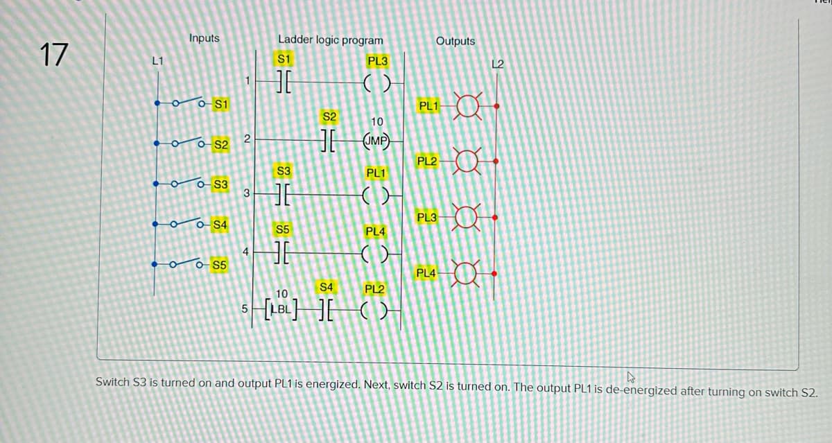
Switch S3 is turned on and output PL1 is energized. Next, switch S2 is turned on. The output PL1 is de-energized after turning on switch S2.


Q: Determine the eight-point DFT of the signal x(n) ={1, 1, 0, 1, 0} and sketch its magnitude and phase
A:
Q: Recommend general considerations when selecting a site for Hydroelectric Power Plant.
A:
Q: Determine Vb for the following circuit using superposition when V1=15 V, V2=6 V, R1=1,000 ,…
A: In this question We need to determine the voltage Vo using the super position theorem. Here two…
Q: Find Vo using Source Transformation Pls show clean and complete solutio
A:
Q: R2 Ww अञ C₁ C2 12 ei ii R1 Co Example 8: Consider the given circuit diagram. Find the transfer…
A: Given data A circuit diagram is given in the problem and contains two capacitors C1 and C2. A…
Q: 10. Determine the voltage drop across, the current flow through, and power on each resistor on the…
A: The required parameters can be calculated by using the node voltage and other parameters can be…
Q: Find Rx for Wheatstone Bridge, if R1-400 and R2=5 K 2 and R3=2 K 2, in case balance of wheatstone…
A:
Q: Identify the Thevenin resistance of the following circuits: a.)the 5 ohm resistor 3 A 2/1 1Ω b.) The…
A:
Q: A vector field S is expressed in rectangular coordinates as: 76 S = - (x − 1)² + (y − 2)² + (z + 1)²…
A: Given,In rectangular coordinates,A vector fiels S is expressed as,S=76x-12+y-22+z+12x-1i+y-2j+z+1k.
Q: ΖΑ(1 Μ 10 Ω Μ 70 3 Ω σν 5Q 9 V 4Ω 16 Ω Μ Μ a 16Ω b
A:
Q: What are the types of Hydroelectric Turbine ?
A:
Q: What are the drawbacks of hydrogen fuel used in fuel cells? What is the most notable technical…
A: We need to tell about drawbacks of hydrogen fuel used in fuel cells and losses of Direct methanol…
Q: Find the z-transform of the number sequence generated by sampling the time function e(t) = 2t every…
A: z-transform This type of transform is sued for the discrete type of signal. The expression for the…
Q: How can wireless Internet contribute to the development of cyber police?
A: Solution: Wireless internet can greatly contribute to the development of cyber police by providing…
Q: 1.6 The power of the signal s(t)=8 cos 20nt (A) 40 (C) 42 T —— 2 + 4 sin(15nt) is (B) 41 (D) 82
A:
Q: Using D flip-flops, design a synchronous counter that counts in the sequence 1, 3, 0, 2, 1, .... The…
A: Given : Synchronous Counter counts the sequence of 1->3->0->2->1 go on repeats. X=1…
Q: A -To To 2 O 2 give the signal below as: To t Determine the fourier series coffiicials of the above…
A: We need to find out Fourier series coefficient for given periodic sequence.
Q: advantages and disadvantages of pi controllers in control systems. Could an example with…
A: We need to tell about advantages and disadvantages of pi controllers in control systems.
Q: A unity feedback system has the open loop transfer function shown below. Find the breakin point.…
A:
Q: O 20K.2 www. 7.5mA 80K 0-4MF 50K2 The switch in the circuit shown has been closed. for a long time…
A: In this given question we need to find out, a) Initial value of capacitor voltage. b)time constant.…
Q: Q.1 Consider the circuit shown in the figure below: V₂ ww+ 50 92 600 Ω ww 300 92 Let V₁ = 40 V and i…
A: Given- A circuit as shown- Vs=40 V &is=0 A. To Find- The value of the voltage across 50 Ω…
Q: A) Given For the electrical system: E(t) B) Determine + + Vc(t) - R R=50, L=0.5H, C=0.01F IL (t)…
A:
Q: Question No. 25 A three-phase, three-stack, variable reluctance step motor has 20 poles on each…
A: here we have to find the step angle of the step motor .
Q: Match the items is List - I (Type of transmission line) with the items in List - II (Type of…
A: Given: Types of transmission line: (a) Short line (b) Medium line (c) Long line Types of distance…
Q: 9. For the circuit shown in Fig. 9, find H(s) = 1o (s)/1, (s). 2Η m 1 + της α ΖΩ 2Η Fig. 9 ΖΩ
A: As per the guidelines of Bartleby we suppose to answer first question only since the remaining…
Q: 2. For the circuit below compute Vth and Rth as seen by nodes A and B. a. For Rth compute this using…
A: In this question We need to determine the Thevenin equivalent circuit across the terminal A and B.…
Q: For the circuit shown, determine the equivalent voltage source in Volts where I=8 A, and R=24 2.…
A: In this question We need to determine the equivalent voltage source. We know Voltage across the…
Q: Design a logic circuit to implement a Moore-type sequence detector to detect each of the following…
A: I have written this solution as handwritten solution. Hope you find the perfect solution.
Q: 2. A facility manager replaces all the TS lights in an office when they have reached 80% of their…
A: Group re-lamping: It is process in which all the old lights are replaced by new ones on…
Q: A system G (s) = has the following transfer function 100(s+5)(s+50) s³(s+10)(s²+3s+10) The type and…
A: Given a system has following transfer function: Gs=100s+5s+50s3s+10s2+3s+10
Q: Q 2. Find the current i, in the circuit shown in fig. 2. 6k R₁ i-? R₂ R₂ 다 3k >1k Fig. 2 36 V B
A:
Q: Design an 8 to 1 MUX using a 4 to 1
A:
Q: 1. An n-type piece of silicon experiences an electric field equal to 0.1 V/um. Note that the…
A: Given data Electric field; E=0.1 V/μm Mobility of electrons; μn=1350 cm2/V·s Mobility of holes;…
Q: Using the circuit. a) Find the Voltage Gain b) If input Vi = 1 Vrms at 1 KHZ, What is the output…
A: NOTE :As per our company guidelines we are supposed to answer first 3 sub-parts only. Kindly re-post…
Q: An iron ring has its mean length of flux path as 60 cm and its cross sectional area as 15 cm^2. Its…
A:
Q: A series RIC circuit consisting of a 25 ohms resistor, 0.8 henry inductor, and a 8.8F capacitor is…
A: In these questions We need to determine the all unknown parameters. We know Inductive Reactance XL…
Q: 9. Reduce the block diagram shown in Figure P5.9 to a single transfer function, 7(s) = C(s)/R(s).…
A:
Q: 1/IMF Problem #5 The initial voltage across the capacitor in the circuit shown is zero. Find vo (t)…
A:
Q: Vp(1) p(t) (V) 5 + R www 10 ΚΩ X t=0 C 2 μF + ... Vo 10-11 t (ms)
A: It is a integrator circuit . Here R=10kohm . C=1uF We need to find transfer function Vo(s)/Vp(s)…
Q: ssume that R4 is the load of the circuit, What is the power in R4 in Watts when =10 V, R1=100,…
A: We need to find out power dissipation in the given resistor for given circuit , so first we will…
Q: Given a standard size 3-input NOR gate followed by two inverters and a load of 100C. What is the…
A: Answer: Given that There are two input NOR which is getting followed by two inverters. The load is…
Q: Suppose r0= OXFOFOFOFO and rl = 0x12345678. Find the value of every register 10-12 after the…
A:
Q: 8.38 Refer to the circuit in Fig. 8.86. Calculate i(t) for t > 0. 5(1-u(t)) A ماليا F= rele www i(t)…
A:
Q: Michael wants to find out the resistance of a resistor. He connects the resistor to a variable…
A: For the given values of potential Difference with its respective value of current passing through…
Q: Question-2 Consider the following circuit, and given: lin(s) Iin (s) = â 2s-1 (s + 1)(s² +25) 400 Ω…
A:
Q: Determine the minimum states state table in Figure P9.24. of the finite-state machine described by…
A: According to the question, we need to Determine the minimum states of the finite-state machine…
Q: A current of 100 mA is applied to a 15 µF capacitor which has an initial voltage across it of 25…
A:
Q: Question 9 An AM receiver is tuned to 980 kHz and uses high-side injection and a 455 kHz IF. What is…
A: Since the question 10 is not a subpart of question 9 as per the guidelines of Bartleby we solve…
Q: Calculate lp for the n-channel MOSFET with VGs = -4 V, lpss = 10 mA and VGS (off) = -8 V.
A: We need to find out drain current.
Q: An iron cored toroid of relative permeability 980 has a mean length of 120 cm and core are of…
A:


Trending now
This is a popular solution!

Step by step
Solved in 3 steps with 2 images


- Create a logic diagram out of this boolean expression. CD+BD+BC+AD+AC+AB Note: All inputs A B C and D must be together.We want to perform subtraction operation in which we need a full subtractor. First draw Truth table for full subtractor. Due to pandemic you are unable to get the desire component. but you have only eight- to-one multiplexers with you. What do you think, can you still perform subtraction operation with multiplexer or not? If yes, draw the logic circuit.answere fast please question from DIGITAL LOGIC DESIGN TOPIC : Designing Combinational Logic You are designing a water level circuit using 74ALS151 (8 to 1 Multiplexer IC)* When input is 0000 that means tank is empty.* When input is 1111 that means tank is full.* When input is below 5, that means water level is low.* So, make a circuit using 74ALS151 Multiplexer IC that shows a "low water" indicator light(by setting an output L to 1) when the water level drops below level 5.
- what a logic function corresponds to the following arrangement? a.L =(S1 OR S2) AND (S3 OR S4)A water drain pump can be activated depending on the status of three switches, one main switch and two secondary switches. The pump is activated if and only if the main switch is turned ON and one of the secondary switch is turned ON. a. Find the minterm expansion in Σ – form. b. Find the maxterm expansion in Π – form. c. Find the minimum SOP expression. d. Find the minimum POS expression. e. Create a logic circuit diagram using the minimum number of gates used.Act 1 problem solving this is a logic circuits and design laboratory subject please help me with this and screenshot all the solution and answers 2. What is the largest binary number that can be expressed with 16 bits? What are the equivalent decimal and hexadecimal numbers? Answer: 16 bits = ________= _______10 = ______16 3. Represent the decimal number 6,248 in: (a) BCD = (b) excess‐3 code = (c) 2421 code =
- Convert the binary number (1011101) to its equivalent decimal and BCD values. (Show you work) Convert the decimal number (478) to its equivalent hexadecimal and binary values. (Show you work) List the next twenty five hex numbers in sequence from (9E7) hex upwards, adding one each time. (Write them horizontally, with comma as separator) Answer the following logic operations : a) 0 . Z’ = b) 1 + W = c) d . d’ = d) b . b = e) X + (X+1)’ = f) 1 + X’ = g) C + B’C’ = h) B + (BC)’ =…Design a circuit called half adder (HA) which adds two 1-bit numbers, a,b and produces 2-bit output, c. a. Draw the truth table of the circuit.b. Find the Boolean functions of each bit of the output.c. Optimize the Boolean functions.d. Draw the logic diagram of the optimized circuits.e. Write the VHDL code of the logic diagrams by using “Dataflow modeling” method f. Simulate the circuits that you have designed in 1.e. Prepare a simulation waveform for you report.g. Produce the RTL schematic for the circuit that you have designed in 1.e.1) (a) Convert binary number 1011101 to a decimal number.(b) Perform the following binary subtraction using the one’s complement method. 11010 -101112) A logic circuit is given below. (a) Draw and fill out a truth table for the logic circuit (Tip: you can add columns for intermediate outputs C, D and E for a help).(b) Derive the Boolean expression from the truth table. 3) The Boolean expression of a logic operation is given below(a) Simplify the Boolean expression using Boolean algebra and De Morgan’s Theorems(b) Draw the circuit to implement the expression you obtain using NAND or NOR gates only.4) In the context of semiconductors, describe the following:(a) Intrinsic and extrinsic semiconductor. (b) Drift velocity of carriers.(c) Band-gap energy.(d) Frequency of light emitted by an LED. 5) Explain how doping a pure silicon crystal with donor impurity atoms makes more charge carriers available for conduction.Does the above doping result in a p-type or n-type semiconductor? Explain…
- . Design a logic circuit that controls an elevator door in a three-story building. The circuithas four inputs. M is a logic signal that indicates when an elevator is moving (M=1) or stopped (M=0).F1, F2 and F3 are floor indicator signals that are normally LOW, and they go HIGH only when theelevator is positioned at the level of that particular floor. For example, when the elevator is lined uplevel with the second floor, F2=1 and F1=F3=0. The circuit output is the OPEN signal which isnormally LOW and is to go HIGH when the elevator door is to be opened.Minimize the following boolean function use five variables k map 1- in sop and draw the logic circuit 2- in pos and draw the logic circuitAn engineer hands you a piece of paper with the following Boolean expression on it, and tells you to build a gate circuit to perform that function: AB+ C(A+B) Draw a logic gate circuit for this function.