т X- +5 V System clock Output Output # 1 # 2

Power System Analysis and Design (MindTap Course List)
6th Edition
ISBN:9781305632134
Author:J. Duncan Glover, Thomas Overbye, Mulukutla S. Sarma
Publisher:J. Duncan Glover, Thomas Overbye, Mulukutla S. Sarma
Chapter8: Symmetrical Components
Section: Chapter Questions
Problem 8.1P

Related questions
Question
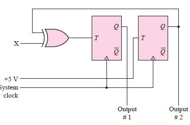
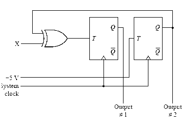
Explain what the circuit does and how it works. (Hint: This circuit is called a 2-bit synchronous binary up-down counter.)
Transcribed Image Text:т
X-
+5 V
System
clock
Output
Output
# 1
# 2
Expert Solution
Step 1
Concept:
A flip flop is an electronic circuit which has two stable states that can be used to store binary data and here the stored data can be changed by applying varying inputs. Flip-flops and latches are the two fundamental building blocks which are been used in computers, communications, and many other types of systems.
Step 2
Given:
Step 3
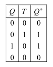
The boolean expression for inputs of flip flops are

The truth table of flip flop is

Step by step
Solved in 5 steps with 4 images

Knowledge Booster


Learn more about
Need a deep-dive on the concept behind this application? Look no further. Learn more about this topic, electrical-engineering and related others by exploring similar questions and additional content below.Recommended textbooks for you
Power System Analysis and Design (MindTap Course …
Electrical Engineering
ISBN:
9781305632134
Author:
J. Duncan Glover, Thomas Overbye, Mulukutla S. Sarma
Publisher:
Cengage Learning

EBK ELECTRICAL WIRING RESIDENTIAL
Electrical Engineering
ISBN:
9781337516549
Author:
Simmons
Publisher:
CENGAGE LEARNING - CONSIGNMENT
Power System Analysis and Design (MindTap Course …
Electrical Engineering
ISBN:
9781305632134
Author:
J. Duncan Glover, Thomas Overbye, Mulukutla S. Sarma
Publisher:
Cengage Learning
EBK ELECTRICAL WIRING RESIDENTIAL
Electrical Engineering
ISBN:
9781337516549
Author:
Simmons
Publisher:
CENGAGE LEARNING - CONSIGNMENT