Task 1: Custom Sequence Counter Using JK Flip Flop, Design a counter circuit that cycles through the sequence: 0, 5, 4, 6, 1, 7, and repeats. Follow these steps: a) State Diagram: Draw a state diagram representing the sequence. Each state should be expressed as a binary number. b) State Table: Create a state table for the counter, detailing current states, next states, and outputs. c) Flip-Flop Input Equations: From the state table, derive the input equations for the flip- flops. Treat any unused states as don't-care conditions. d) Simplification using K-maps: Use Karnaugh maps to simplify the flip-flop input equations. Optionally, verify your simplifications using Multisim. e) Circuit Diagram: Draw the circuit diagram. Task 2: 3-bit Up/Down Counter Using Flip Flop of your choice, design a 3-bit counter that counts up or down based on an input signal X. The counter should behave as follows: Initial State: On powerup, the counter starts at 0. Count Up (X=1): Sequence progresses through 1, 2, 3, 4, 5, 6, 7, 0, and repeats. Count Down (X=0): Sequence reverses direction. For example, if the counter is at state 4 when X becomes 0, it counts down through 3, 2, 1, 0, 7, 6, 5, 4 etc. a) State Diagram: Draw a state diagram for both counting up and counting down. Each state should be expressed as a binary number. b) State Table: Generate a state table indicating current states, next states, and the input condition X. c) Flip-Flop Input Equations: Write down the input equations for the flip-flops from the Next State entries. d) Simplification using K-maps: Simplify the input equations using Karnaugh maps. Optionally, verify these using Multisim. e) Circuit Diagram: Draw the circuit diagram.
Task 1: Custom Sequence Counter Using JK Flip Flop, Design a counter circuit that cycles through the sequence: 0, 5, 4, 6, 1, 7, and repeats. Follow these steps: a) State Diagram: Draw a state diagram representing the sequence. Each state should be expressed as a binary number. b) State Table: Create a state table for the counter, detailing current states, next states, and outputs. c) Flip-Flop Input Equations: From the state table, derive the input equations for the flip- flops. Treat any unused states as don't-care conditions. d) Simplification using K-maps: Use Karnaugh maps to simplify the flip-flop input equations. Optionally, verify your simplifications using Multisim. e) Circuit Diagram: Draw the circuit diagram. Task 2: 3-bit Up/Down Counter Using Flip Flop of your choice, design a 3-bit counter that counts up or down based on an input signal X. The counter should behave as follows: Initial State: On powerup, the counter starts at 0. Count Up (X=1): Sequence progresses through 1, 2, 3, 4, 5, 6, 7, 0, and repeats. Count Down (X=0): Sequence reverses direction. For example, if the counter is at state 4 when X becomes 0, it counts down through 3, 2, 1, 0, 7, 6, 5, 4 etc. a) State Diagram: Draw a state diagram for both counting up and counting down. Each state should be expressed as a binary number. b) State Table: Generate a state table indicating current states, next states, and the input condition X. c) Flip-Flop Input Equations: Write down the input equations for the flip-flops from the Next State entries. d) Simplification using K-maps: Simplify the input equations using Karnaugh maps. Optionally, verify these using Multisim. e) Circuit Diagram: Draw the circuit diagram.

Chapter22: Sequence Control
Section: Chapter Questions
Problem 6SQ: Draw a symbol for a solid-state logic element AND.

Related questions
Question
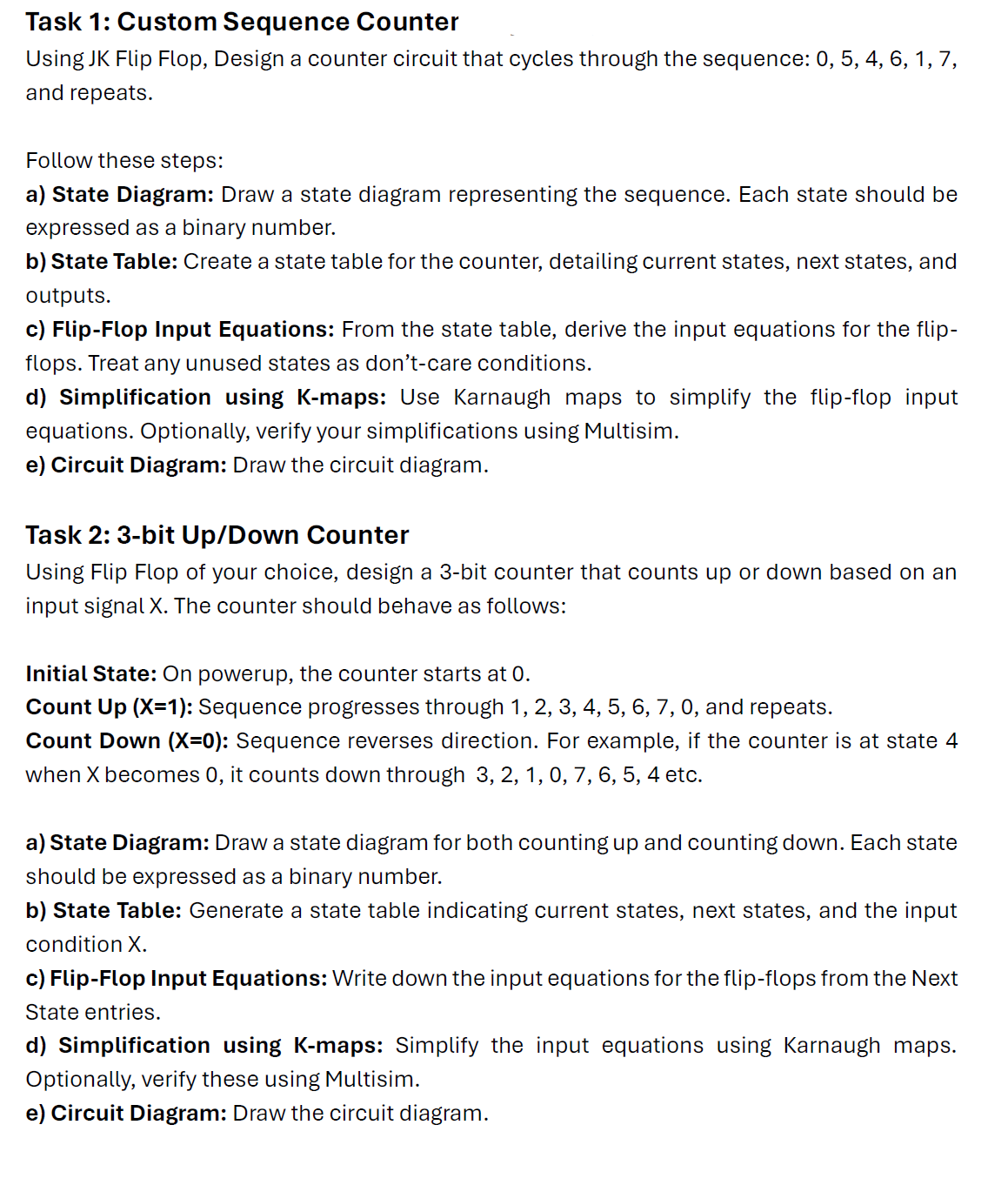
Transcribed Image Text:Task 1: Custom Sequence Counter
Using JK Flip Flop, Design a counter circuit that cycles through the sequence: 0, 5, 4, 6, 1, 7,
and repeats.
Follow these steps:
a) State Diagram: Draw a state diagram representing the sequence. Each state should be
expressed as a binary number.
b) State Table: Create a state table for the counter, detailing current states, next states, and
outputs.
c) Flip-Flop Input Equations: From the state table, derive the input equations for the flip-
flops. Treat any unused states as don't-care conditions.
d) Simplification using K-maps: Use Karnaugh maps to simplify the flip-flop input
equations. Optionally, verify your simplifications using Multisim.
e) Circuit Diagram: Draw the circuit diagram.
Task 2: 3-bit Up/Down Counter
Using Flip Flop of your choice, design a 3-bit counter that counts up or down based on an
input signal X. The counter should behave as follows:
Initial State: On powerup, the counter starts at 0.
Count Up (X=1): Sequence progresses through 1, 2, 3, 4, 5, 6, 7, 0, and repeats.
Count Down (X=0): Sequence reverses direction. For example, if the counter is at state 4
when X becomes 0, it counts down through 3, 2, 1, 0, 7, 6, 5, 4 etc.
a) State Diagram: Draw a state diagram for both counting up and counting down. Each state
should be expressed as a binary number.
b) State Table: Generate a state table indicating current states, next states, and the input
condition X.
c) Flip-Flop Input Equations: Write down the input equations for the flip-flops from the Next
State entries.
d) Simplification using K-maps: Simplify the input equations using Karnaugh maps.
Optionally, verify these using Multisim.
e) Circuit Diagram: Draw the circuit diagram.
Expert Solution
This question has been solved!
Explore an expertly crafted, step-by-step solution for a thorough understanding of key concepts.

Step by step
Solved in 2 steps with 2 images

Recommended textbooks for you