The amplifier circuit below has a single ac input and two ac outputs. Assuming transistor parameters of ß = 200 and VBE = 0.7 V: (2-a) Determine the Q point. (2-b) Is the transistor in the active region? Explain thoroughly. (2-c) Construct the T-model of the transistor with all parameters labelled and evaluated. Assume room temperature.
The amplifier circuit below has a single ac input and two ac outputs. Assuming transistor parameters of ß = 200 and VBE = 0.7 V: (2-a) Determine the Q point. (2-b) Is the transistor in the active region? Explain thoroughly. (2-c) Construct the T-model of the transistor with all parameters labelled and evaluated. Assume room temperature.

Power System Analysis and Design (MindTap Course List)
6th Edition
ISBN:9781305632134
Author:J. Duncan Glover, Thomas Overbye, Mulukutla S. Sarma
Publisher:J. Duncan Glover, Thomas Overbye, Mulukutla S. Sarma
Chapter12: Power System Controls
Section: Chapter Questions
Problem 12.3P

Related questions

Question
Please, help me to solve the first three branches (a, b, and c)
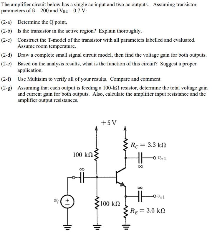
Transcribed Image Text:The amplifier circuit below has a single ac input and two ac outputs. Assuming transistor
parameters of ß= 200 and VBE = 0.7 V:
(2-a) Determine the Q point.
(2-b) Is the transistor in the active region? Explain thoroughly.
(2-c) Construct the T-model of the transistor with all parameters labelled and evaluated.
Assume room temperature.
(2-d) Draw a complete small signal circuit model, then find the voltage gain for both outputs.
(2-e) Based on the analysis results, what is the function of this circuit? Suggest a proper
application.
(2-f)
Use Multisim to verify all of your results. Compare and comment.
(2-g) Assuming that each output is feeding a 100-k2 resistor, determine the total voltage gain
and current gain for both outputs. Also, calculate the amplifier input resistance and the
amplifier output resistances.
+5V
Rc = 3.3 kf
100 kN
O Vo2
v; ( +
100 k
RE = 3.6 kn
Expert Solution
This question has been solved!
Explore an expertly crafted, step-by-step solution for a thorough understanding of key concepts.

Step by step
Solved in 4 steps with 3 images

Knowledge Booster


Learn more about
Need a deep-dive on the concept behind this application? Look no further. Learn more about this topic, electrical-engineering and related others by exploring similar questions and additional content below.Recommended textbooks for you
Power System Analysis and Design (MindTap Course …
Electrical Engineering
ISBN:
9781305632134
Author:
J. Duncan Glover, Thomas Overbye, Mulukutla S. Sarma
Publisher:
Cengage Learning

EBK ELECTRICAL WIRING RESIDENTIAL
Electrical Engineering
ISBN:
9781337516549
Author:
Simmons
Publisher:
CENGAGE LEARNING - CONSIGNMENT
Power System Analysis and Design (MindTap Course …
Electrical Engineering
ISBN:
9781305632134
Author:
J. Duncan Glover, Thomas Overbye, Mulukutla S. Sarma
Publisher:
Cengage Learning
EBK ELECTRICAL WIRING RESIDENTIAL
Electrical Engineering
ISBN:
9781337516549
Author:
Simmons
Publisher:
CENGAGE LEARNING - CONSIGNMENT