The astable 555 Timer operates as follows: 1) When the timer is initially turned on, the capacitor C is completely discharged and begins charging through the combined resistance of R1 and R2 (series) and the output is equivalent to the source voltage, Vs. 2) When the voltage on the capacitor C reaches 2/3rd of the supply voltage, the internal circuitry of the 555 Timer IC causes the DIS pin to go to 0V, causing the capacitor C to discharge through resistor R2 and the output to go to 0V. 3) Once the voltage on the capacitor C falls to 1/3rd of the supply voltage, the internal circuitry of the 555 Timer IC causes the DIS pin to no longer be 0V, and the capacitor C begins charging through resistors R1 and R2 and setting the output voltage back to the source voltage.NOTE: if the capacitor is initially charged (Vo), the capacitor charging equation becomes: Vc= Vs+(Vo―Vs)e^(-t/(RC)) 4)Steps 2 and 3 are repeated until power is removed from the circuit and the capacitor fully discharges. Find The amount of time that the output of the 555 Timer is high when the circuit is first powered on, The amount of time that the output of the 555 Timer is low during a regular cycle of the output, and the amount of time that the output of the 555 Timer is high during a regular cycle of the output.
The astable 555 Timer operates as follows: 1) When the timer is initially turned on, the capacitor C is completely discharged and begins charging through the combined resistance of R1 and R2 (series) and the output is equivalent to the source voltage, Vs. 2) When the voltage on the capacitor C reaches 2/3rd of the supply voltage, the internal circuitry of the 555 Timer IC causes the DIS pin to go to 0V, causing the capacitor C to discharge through resistor R2 and the output to go to 0V. 3) Once the voltage on the capacitor C falls to 1/3rd of the supply voltage, the internal circuitry of the 555 Timer IC causes the DIS pin to no longer be 0V, and the capacitor C begins charging through resistors R1 and R2 and setting the output voltage back to the source voltage.NOTE: if the capacitor is initially charged (Vo), the capacitor charging equation becomes: Vc= Vs+(Vo―Vs)e^(-t/(RC)) 4)Steps 2 and 3 are repeated until power is removed from the circuit and the capacitor fully discharges. Find The amount of time that the output of the 555 Timer is high when the circuit is first powered on, The amount of time that the output of the 555 Timer is low during a regular cycle of the output, and the amount of time that the output of the 555 Timer is high during a regular cycle of the output.

Introductory Circuit Analysis (13th Edition)
13th Edition
ISBN:9780133923605
Author:Robert L. Boylestad
Publisher:Robert L. Boylestad
Chapter1: Introduction
Section: Chapter Questions
Problem 1P: Visit your local library (at school or home) and describe the extent to which it provides literature...

Related questions
Question
The astable 555 Timer operates as follows:
1) When the timer is initially turned on, the capacitor C is completely discharged and begins charging through the combined resistance of R1 and R2 (series) and the output is equivalent to the source voltage, Vs.
2) When the voltage on the capacitor C reaches 2/3rd of the supply voltage, the internal circuitry of the 555 Timer IC causes the DIS pin to go to 0V, causing the capacitor C to discharge through resistor R2 and the output to go to 0V.
3) Once the voltage on the capacitor C falls to 1/3rd of the supply voltage, the internal circuitry of the 555 Timer IC causes the DIS pin to no longer be 0V, and the capacitor C begins charging through resistors R1 and R2 and setting the output voltage back to the source voltage.NOTE: if the capacitor is initially charged (Vo), the capacitor charging equation becomes: Vc= Vs+(Vo―Vs)e^(-t/(RC))
4)Steps 2 and 3 are repeated until power is removed from the circuit and the capacitor fully discharges.
Find The amount of time that the output of the 555 Timer is high when the circuit is first powered on, The amount of time that the output of the 555 Timer is low during a regular cycle of the output, and the amount of time that the output of the 555 Timer is high during a regular cycle of the output.
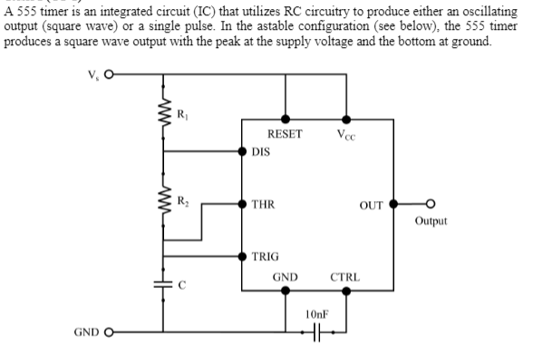
Transcribed Image Text:A 555 timer is an integrated circuit (IC) that utilizes RC circuitry to produce either an oscillating
output (square wave) or a single pulse. In the astable configuration (see below), the 555 timer
produces a square wave output with the peak at the supply voltage and the bottom at ground.
v, O
RESET
DIS
THR
OUT
Output
TRIG
GND
CTRL
10nF
GND
Expert Solution
This question has been solved!
Explore an expertly crafted, step-by-step solution for a thorough understanding of key concepts.

This is a popular solution!

Trending now
This is a popular solution!

Step by step
Solved in 2 steps with 4 images

Knowledge Booster


Learn more about
Need a deep-dive on the concept behind this application? Look no further. Learn more about this topic, electrical-engineering and related others by exploring similar questions and additional content below.Recommended textbooks for you
Introductory Circuit Analysis (13th Edition)
Electrical Engineering
ISBN:
9780133923605
Author:
Robert L. Boylestad
Publisher:
PEARSON

Delmar's Standard Textbook Of Electricity
Electrical Engineering
ISBN:
9781337900348
Author:
Stephen L. Herman
Publisher:
Cengage Learning

Programmable Logic Controllers
Electrical Engineering
ISBN:
9780073373843
Author:
Frank D. Petruzella
Publisher:
McGraw-Hill Education
Introductory Circuit Analysis (13th Edition)
Electrical Engineering
ISBN:
9780133923605
Author:
Robert L. Boylestad
Publisher:
PEARSON
Delmar's Standard Textbook Of Electricity
Electrical Engineering
ISBN:
9781337900348
Author:
Stephen L. Herman
Publisher:
Cengage Learning
Programmable Logic Controllers
Electrical Engineering
ISBN:
9780073373843
Author:
Frank D. Petruzella
Publisher:
McGraw-Hill Education

Fundamentals of Electric Circuits
Electrical Engineering
ISBN:
9780078028229
Author:
Charles K Alexander, Matthew Sadiku
Publisher:
McGraw-Hill Education

Electric Circuits. (11th Edition)
Electrical Engineering
ISBN:
9780134746968
Author:
James W. Nilsson, Susan Riedel
Publisher:
PEARSON

Engineering Electromagnetics
Electrical Engineering
ISBN:
9780078028151
Author:
Hayt, William H. (william Hart), Jr, BUCK, John A.
Publisher:
Mcgraw-hill Education,