The beam shown will be constructed from a standard steel W-shape using an allowable bending stress of 40.4 ksi. Assume P = 51 kips, L1=6.6 ft, and L2=19.8 ft. (a) Determine the minimum section modulus required for this beam. (b) From the table below, select the lightest W shape that can be used for this beam. (c) What is the total weight of the steel beam itself (i.e., not including the loads that
The beam shown will be constructed from a standard steel W-shape using an allowable bending stress of 40.4 ksi. Assume P = 51 kips, L1=6.6 ft, and L2=19.8 ft. (a) Determine the minimum section modulus required for this beam. (b) From the table below, select the lightest W shape that can be used for this beam. (c) What is the total weight of the steel beam itself (i.e., not including the loads that

Mechanics of Materials (MindTap Course List)
9th Edition
ISBN:9781337093347
Author:Barry J. Goodno, James M. Gere
Publisher:Barry J. Goodno, James M. Gere
Chapter5: Stresses In Beams (basic Topics)
Section: Chapter Questions
Problem 5.6.13P: A two-axle carriage that is part of an over head traveling crane in a testing laboratory moves...

Related questions
Question
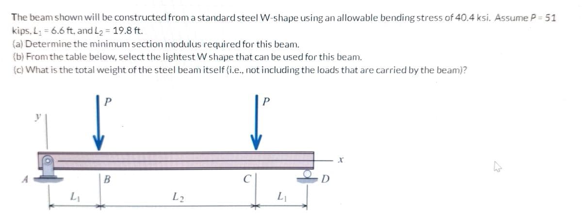
The beam shown will be constructed from a standard steel W-shape using an allowable bending stress of 40.4 ksi. Assume P = 51 kips, L1=6.6 ft, and L2=19.8 ft.
(a) Determine the minimum section modulus required for this beam.
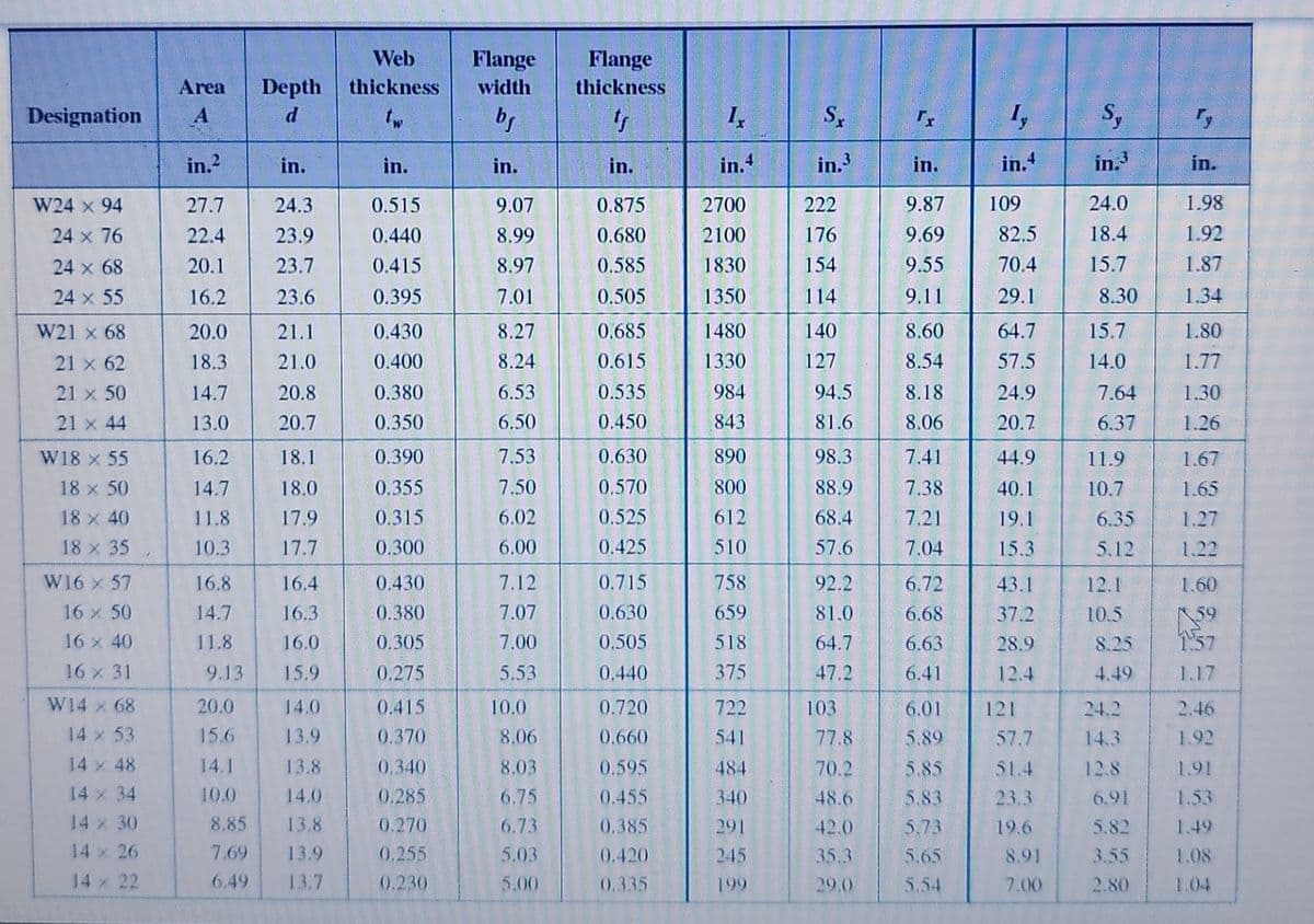
(b) From the table below, select the lightest W shape that can be used for this beam.
(c) What is the total weight of the steel beam itself (i.e., not including the loads that are carried by the beam)?
Transcribed Image Text:The beam shown will be constructed from a standard steel W-shape using an allowable bending stress of 40.4 ksi. Assume P = 51
kips, L₁ = 6.6 ft, and L₂ = 19.8 ft.
(a) Determine the minimum section modulus required for this beam.
(b) From the table below, select the lightest W shape that can be used for this beam.
(c) What is the total weight of the steel beam itself (i.e., not including the loads that are carried by the beam)?
L₁
P
B
L2
с
P
L₁
-D
X
A
Transcribed Image Text:Designation A
W24 x 94
24 × 76
24 × 68
24 × 55
W21 x 68
21 x 62
21 x 50
21 x 44
W18 x 55
18 x 50
18 × 40
18 x 35
W16 x 57
16 x 50
16 x 40
16 x 31
Area Depth
d
W14 × 68
14 × 53
14 x 48
14 × 34
14 x 30
14 x 26
in.2
27.7
22.4
20.1
16.2
20.0
18.3
14.7
13.0
16.2
14.7
11.8
10.3
16.8
14.7
11.8
in.
24.3
23.9
23.7
23.6
20.0
15.6
14.1
10.0
21.1
21.0
20.8
20.7
16.4
16.3
16.0
9.13 15.9
18.1
18.0
17.9
17.7
14.0
13.9
13.8
14.0
8.85
13.8
7.69
13.9
6.49 13.7
Web
thickness
tw
in.
0.515
0.440
0.415
0.395
0.430
0.400
0.380
0.350
0.390
0.355
0.315
0.300
0.430
0.380
0.305
0.275
0.415
0.370
0.340
0.285
0.270
0.255
0.230
Flange
width
bf
in.
9.07
8.99
8.97
7.01
8.27
8.24
6.53
6.50
7.53
7.50
6.02
6.00
7.12
7.07
7.00
5.53
10.0
8.06
8.03
6.75
6.73
5.03
5.00
Flange
thickness
tr
in.
0.875
0.680
0.585
0.505
0.685
0.615
0.535
0.450
0.630
0.570
0.525
0.425
0.715
0.630
0.505
0.440
0.720
0.660
0.595
0.455
0.385
0.420
0.335
Ix
in.4
2700
2100
1830
1350
1480
1330
984
843
890
800
612
510
758
659
518
375
722
541
484
340
291
245
199
Sx
in.3
222
176
154
114
140
127
94.5
81.6
98.3
88.9
68.4
57.6
92.2
81.0
64.7
47.2
103
77.8
70.2
48.6
42.0
35.3
29.0
in.
9.87
9.69
9.55
9.11
8.60
8.54
8.18
8.06
7.41
7.38
7.21
7.04
6.72
6.68
6.63
6.41
6.01
5.89
5.85
5.83
5.73
5.65
5.54
Ty
in.4
109
82.5
70.4
29.1
64.7
57.5
24.9
20.7
44.9
40.1
19.1
15.3
43.1
37.2
28.9
12.4
121
57.7
51.4
23.3
19.6
8.91
7.00
Sy
in.3
24.0
18.4
15.7
8.30
15.7
14.0
7.64
6.37
11.9
10.7
6.35
5.12
12.1
10.5
8.25
4.49
24.2
14.3
12.8
6.91
5.82
3.55
2.80
Ty
in.
1.98
1.92
1.87
1.34
1.80
1.77
1.30
1.26
1.67
1.65
1.27
1.22
1.60
1.57
1.17
2.46
1.92
1.53
1.49
1.08
1.04
Expert Solution
This question has been solved!
Explore an expertly crafted, step-by-step solution for a thorough understanding of key concepts.

This is a popular solution!

Trending now
This is a popular solution!

Step by step
Solved in 4 steps with 1 images

Knowledge Booster


Learn more about
Need a deep-dive on the concept behind this application? Look no further. Learn more about this topic, mechanical-engineering and related others by exploring similar questions and additional content below.Recommended textbooks for you
Mechanics of Materials (MindTap Course List)
Mechanical Engineering
ISBN:
9781337093347
Author:
Barry J. Goodno, James M. Gere
Publisher:
Cengage Learning
Mechanics of Materials (MindTap Course List)
Mechanical Engineering
ISBN:
9781337093347
Author:
Barry J. Goodno, James M. Gere
Publisher:
Cengage Learning