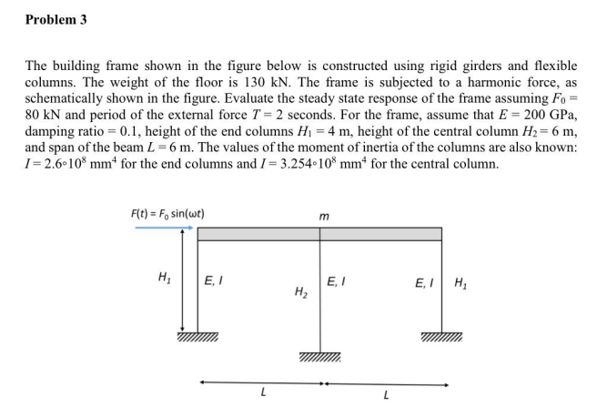
The building frame shown in the figure below is constructed using rigid girders and flexible columns. The weight of the floor is 130 kN. The frame is subjected to a harmonic force, as schematically shown in the figure. Evaluate the steady state response of the frame assuming Fo = 80 kN and period of the external force T = 2 seconds. For the frame, assume that E = 200 GPa, damping ratio = 0.1, height of the end columns Hj = 4 m, height of the central column H2= 6 m, and span of the beam L = 6 m. The values of the moment of inertia of the columns are also known: = 2.6 10* mm* for the end columns and I= 3.254•10* mm“ for the central column. F(t) = Fo sin(wt)
The building frame shown in the figure below is constructed using rigid girders and flexible columns. The weight of the floor is 130 kN. The frame is subjected to a harmonic force, as schematically shown in the figure. Evaluate the steady state response of the frame assuming Fo = 80 kN and period of the external force T = 2 seconds. For the frame, assume that E = 200 GPa, damping ratio = 0.1, height of the end columns Hj = 4 m, height of the central column H2= 6 m, and span of the beam L = 6 m. The values of the moment of inertia of the columns are also known: = 2.6 10* mm* for the end columns and I= 3.254•10* mm“ for the central column. F(t) = Fo sin(wt)

Chapter2: Loads On Structures
Section: Chapter Questions
Problem 1P

Related questions

Question
Transcribed Image Text:Problem 3
The building frame shown in the figure below is constructed using rigid girders and flexible
columns. The weight of the floor is 130 kN. The frame is subjected to a harmonic force, as
schematically shown in the figure. Evaluate the steady state response of the frame assuming Fo =
80 kN and period of the external force T = 2 seconds. For the frame, assume that E = 200 GPa,
damping ratio = 0.1, height of the end columns H1 = 4 m, height of the central column H2= 6 m,
and span of the beam L = 6 m. The values of the moment of inertia of the columns are also known:
I= 2.6 10* mm* for the end columns and I = 3.254 10* mm“ for the central column.
F(t) = F, sin(wt)
m
E, I
E, I
H2
E, I H,
L
ui
Expert Solution
This question has been solved!
Explore an expertly crafted, step-by-step solution for a thorough understanding of key concepts.

This is a popular solution!

Trending now
This is a popular solution!

Step by step
Solved in 3 steps

Knowledge Booster


Learn more about
Need a deep-dive on the concept behind this application? Look no further. Learn more about this topic, civil-engineering and related others by exploring similar questions and additional content below.Recommended textbooks for you

Structural Analysis (10th Edition)
Civil Engineering
ISBN:
9780134610672
Author:
Russell C. Hibbeler
Publisher:
PEARSON

Principles of Foundation Engineering (MindTap Cou…
Civil Engineering
ISBN:
9781337705028
Author:
Braja M. Das, Nagaratnam Sivakugan
Publisher:
Cengage Learning
Structural Analysis (10th Edition)
Civil Engineering
ISBN:
9780134610672
Author:
Russell C. Hibbeler
Publisher:
PEARSON
Principles of Foundation Engineering (MindTap Cou…
Civil Engineering
ISBN:
9781337705028
Author:
Braja M. Das, Nagaratnam Sivakugan
Publisher:
Cengage Learning

Fundamentals of Structural Analysis
Civil Engineering
ISBN:
9780073398006
Author:
Kenneth M. Leet Emeritus, Chia-Ming Uang, Joel Lanning
Publisher:
McGraw-Hill Education


Traffic and Highway Engineering
Civil Engineering
ISBN:
9781305156241
Author:
Garber, Nicholas J.
Publisher:
Cengage Learning