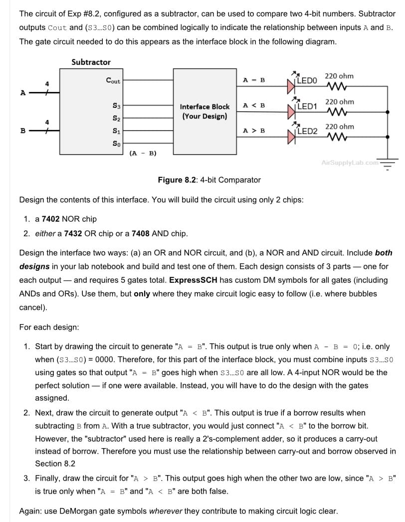
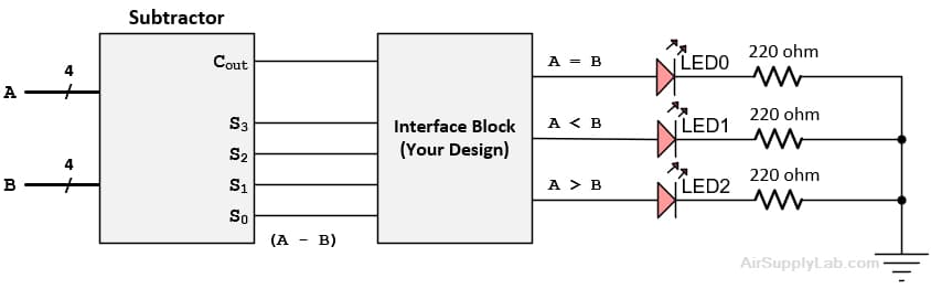
The circuit of Exp #8.2, configured as a subtractor, can be used to compare two 4-bit numbers. Subtractor outputs Cout and (S3.so) can be combined logically to indicate the relationship between inputs A and B. The gate circuit needed to do this appears as the interface block in the following diagram. Subtractor 220 ohm Cout A - B LEDO 4 A S3 A < B LED1 220 ohm Interface Block S2 (Your Design) 220 ohm B S1 A > B LED2 So (A - B) AirSupplyLab.com Figure 8.2: 4-bit Comparator Design the contents of this interface. You will build the circuit using only 2 chips: 1. a 7402 NOR chip 2. either a 7432 OR chip or a 7408 AND chip. Design the interface two ways: (a) an OR and NOR circuit, and (b), a NOR and AND circuit. Include both designs in your lab notebook and build and test one of them. Each design consists of 3 parts – one for each output – and requires 5 gates total. ExpressSCH has custom DM symbols for all gates (including ANDS and ORs). Use them, but only where they make circuit logic easy to follow (i.e. where bubbles cancel). For each design: 1. Start by drawing the circuit to generate "A = B". This output is true only when A - B = 0; i.e. only when (S3.so) = 0000. Therefore, for this part of the interface block, you must combine inputs s3.so using gates so that output "A = B" goes high when s3.so are all low. A 4-input NOR would be the perfect solution – if one were available. Instead, you will have to do the design with the gates assigned. 2. Next, draw the circuit to generate output "A < B". This output is true if a borrow results when subtracting B from A. With a true subtractor, you would just connect "A < B" to the borrow bit. However, the "subtractor" used here is really a 2's-complement adder, so it produces a carry-out instead of borrow. Therefore you must use the relationship between carry-out and borrow observed in Section 8.2 3. Finally, draw the circuit for "A > B". This output goes high when the other two are low, since "A > B" is true only when "A = B" and "A < B" are both false. Again: use DeMorgan gate symbols wherever they contribute to making circuit logic clear.
The circuit of Exp #8.2, configured as a subtractor, can be used to compare two 4-bit numbers. Subtractor outputs Cout and (S3.so) can be combined logically to indicate the relationship between inputs A and B. The gate circuit needed to do this appears as the interface block in the following diagram. Subtractor 220 ohm Cout A - B LEDO 4 A S3 A < B LED1 220 ohm Interface Block S2 (Your Design) 220 ohm B S1 A > B LED2 So (A - B) AirSupplyLab.com Figure 8.2: 4-bit Comparator Design the contents of this interface. You will build the circuit using only 2 chips: 1. a 7402 NOR chip 2. either a 7432 OR chip or a 7408 AND chip. Design the interface two ways: (a) an OR and NOR circuit, and (b), a NOR and AND circuit. Include both designs in your lab notebook and build and test one of them. Each design consists of 3 parts – one for each output – and requires 5 gates total. ExpressSCH has custom DM symbols for all gates (including ANDS and ORs). Use them, but only where they make circuit logic easy to follow (i.e. where bubbles cancel). For each design: 1. Start by drawing the circuit to generate "A = B". This output is true only when A - B = 0; i.e. only when (S3.so) = 0000. Therefore, for this part of the interface block, you must combine inputs s3.so using gates so that output "A = B" goes high when s3.so are all low. A 4-input NOR would be the perfect solution – if one were available. Instead, you will have to do the design with the gates assigned. 2. Next, draw the circuit to generate output "A < B". This output is true if a borrow results when subtracting B from A. With a true subtractor, you would just connect "A < B" to the borrow bit. However, the "subtractor" used here is really a 2's-complement adder, so it produces a carry-out instead of borrow. Therefore you must use the relationship between carry-out and borrow observed in Section 8.2 3. Finally, draw the circuit for "A > B". This output goes high when the other two are low, since "A > B" is true only when "A = B" and "A < B" are both false. Again: use DeMorgan gate symbols wherever they contribute to making circuit logic clear.

Introductory Circuit Analysis (13th Edition)
13th Edition
ISBN:9780133923605
Author:Robert L. Boylestad
Publisher:Robert L. Boylestad
Chapter1: Introduction
Section: Chapter Questions
Problem 1P: Visit your local library (at school or home) and describe the extent to which it provides literature...

Related questions

Question
100%
Help me please
Transcribed Image Text:The circuit of Exp #8.2, configured as a subtractor, can be used to compare two 4-bit numbers. Subtractor
outputs Cout and (S3.so) can be combined logically to indicate the relationship between inputs A and B.
The gate circuit needed to do this appears as the interface block in the following diagram.
Subtractor
220 ohm
Cout
A - B
|LEDO
4
A
220 ohm
S3
Interface Block
A < B
VLED1
(Your Design)
220 ohm
S1
A > B
LED2
So
(А - В)
AirSupplyLab.com
Figure 8.2: 4-bit Comparator
Design the contents of this interface. You will build the circuit using only 2 chips:
1. a 7402 NOR chip
2. either a 7432 OR chip or a 7408 AND chip.
Design the interface two ways: (a) an OR and NOR circuit, and (b), a NOR and AND circuit. Include both
designs in your lab notebook and build and test one of them. Each design consists of 3 parts – one for
each output – and requires 5 gates total. ExpressSCH has custom DM symbols for all gates (including
ANDS and ORs). Use them, but only where they make circuit logic easy to follow (i.e. where bubbles
cancel).
For each design:
1. Start by drawing the circuit to generate "A = B". This output is true only when A - B = 0; i.e. only
when (S3.so) = 0000. Therefore, for this part of the interface block, you must combine inputs s3.so
using gates so that output "A = B" goes high when s3.so are all low. A 4-input NOR would be the
perfect solution – if one were available. Instead, you will have to do the design with the gates
assigned.
2. Next, draw the circuit to generate output "A < B". This output is true if a borrow results when
subtracting B from A. With a true subtractor, you would just connect "A < B" to the borrow bit.
However, the "subtractor" used here is really a 2's-complement adder, so it produces a carry-out
instead of borrow. Therefore you must use the relationship between carry-out and borrow observed in
Section 8.2
3. Finally, draw the circuit for "A > B". This output goes high when the other two are low, since "A > B"
is true only when "A = B" and "A < B" are both false.
Again: use DeMorgan gate symbols wherever they contribute to making circuit logic clear.
Transcribed Image Text:Subtractor
220 ohm
Cout
A = B
LEDO
4
A
220 ohm
S3
A < B
|LED1
Interface Block
S2
(Your Design)
220 ohm
в
S1
A > B
LED2
So
(A - B)
AirSupplyLab.com
Expert Solution
This question has been solved!
Explore an expertly crafted, step-by-step solution for a thorough understanding of key concepts.

This is a popular solution!

Trending now
This is a popular solution!

Step by step
Solved in 4 steps with 3 images

Knowledge Booster


Learn more about
Need a deep-dive on the concept behind this application? Look no further. Learn more about this topic, electrical-engineering and related others by exploring similar questions and additional content below.Recommended textbooks for you
Introductory Circuit Analysis (13th Edition)
Electrical Engineering
ISBN:
9780133923605
Author:
Robert L. Boylestad
Publisher:
PEARSON

Delmar's Standard Textbook Of Electricity
Electrical Engineering
ISBN:
9781337900348
Author:
Stephen L. Herman
Publisher:
Cengage Learning

Programmable Logic Controllers
Electrical Engineering
ISBN:
9780073373843
Author:
Frank D. Petruzella
Publisher:
McGraw-Hill Education
Introductory Circuit Analysis (13th Edition)
Electrical Engineering
ISBN:
9780133923605
Author:
Robert L. Boylestad
Publisher:
PEARSON
Delmar's Standard Textbook Of Electricity
Electrical Engineering
ISBN:
9781337900348
Author:
Stephen L. Herman
Publisher:
Cengage Learning
Programmable Logic Controllers
Electrical Engineering
ISBN:
9780073373843
Author:
Frank D. Petruzella
Publisher:
McGraw-Hill Education

Fundamentals of Electric Circuits
Electrical Engineering
ISBN:
9780078028229
Author:
Charles K Alexander, Matthew Sadiku
Publisher:
McGraw-Hill Education

Electric Circuits. (11th Edition)
Electrical Engineering
ISBN:
9780134746968
Author:
James W. Nilsson, Susan Riedel
Publisher:
PEARSON

Engineering Electromagnetics
Electrical Engineering
ISBN:
9780078028151
Author:
Hayt, William H. (william Hart), Jr, BUCK, John A.
Publisher:
Mcgraw-hill Education,