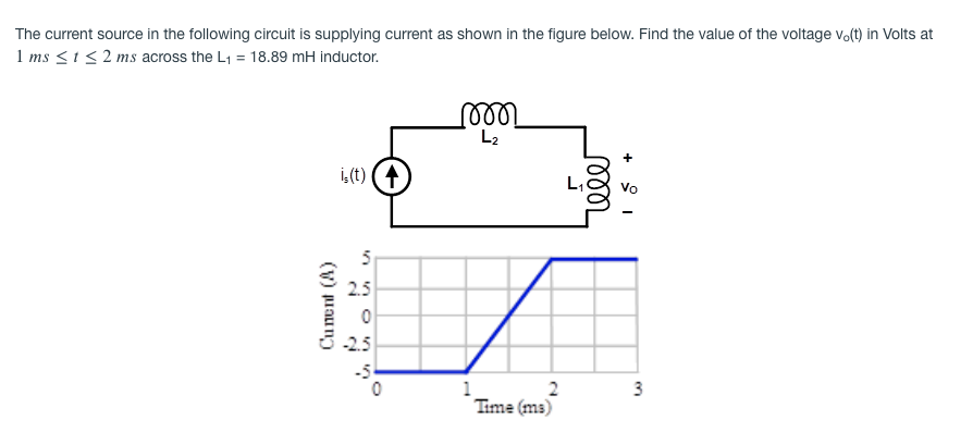
The current source in the following circuit is supplying current as shown in the figure below. Find the value of the voltage vo(t) in Volts at 1 ms <1< 2 ms across the L1 = 18.89 mH inductor. L2 i,(t) (4 L, Vo 2.5 -2.5 -5 1 2 Time (ms) Cunent (A) 3.


Q: In the circuit below, Rq = 1 N. R2 = 5 N, L = 1 H, C = 3 F, E = 15 V. Solve for the current through…
A:
Q: Problem 4 In the given circuit, the switch has been in position A for a long time and switches to…
A:
Q: The circuit parameters in the circuit are R=4800 Ω, L=64 mH, C=4 nF, and vg=−72 V.1. Express vo(t)…
A: Hello. Since your question has multiple sub-parts, we will solve first three sub-parts for you. If…
Q: Q3/ For the circuit shown, the switch S is closed at t-0, and the voltage readings for capacitor…
A: Given:
Q: 2. Please find the time constant and capacitance value (C) of a simple RC circuit by using its…
A: The capacitor stores the charge in the form of voltage. The current can be exponential decaying or…
Q: Questions 39 Given: C, L The circuit below is under steady DC conditions. 6 N C F 8 H lll 1020° A L…
A:
Q: Q.34: The switch in the circuit shown in figure beside has been closed for a long time, and then…
A: We have to determine the value of Vo voltage across capacitor
Q: Consider a circuit composed of a battery (ɛ= 20 V), a resistor (R = 10 Q) and an inductor (L = 1 mH)…
A: The circuit for time t<0 is drawn as shown in the figure below.
Q: Consider the circuit depicted in Figure. If vs(t) =-8 + 2u(t) V, determine 1H ic 2 m F VC 10 0 Q3:…
A: For t<0, u(t)=0 ∴ vs(0-) = -8 volts VL(0-) = 0 volt VL is voltage across the inductor.
Q: Consider the circuit shown in the Figure, if Is = 11 A, R1=5Q and R2 = 30, the energy stored in the…
A: Given circuit
Q: The circuit elements in the circuit L=50 mH, and C=0.2 μF. The initial inductor current is−45 mA and…
A: From the given circuit the initial inductor current is −45 mA and the initial capacitor voltage is…
Q: The voltage v(t) describe by the equation below is a cross a 0.5 uF capacitor . C 0, t <0s; Os…
A: Given data: C=0.5 μF
Q: 1. Transient analysis t=0 R2=20 R1=30 V1=45 V (+ R3=60 L=7 mH V2=26 V (+ 0 the switch is The switch…
A:
Q: B-For the circuit shown, the switch S is closed at t-0, and the voltage readings for capacitor (Vc)…
A: From given details we will find out the capacitor and E and time constant value .
Q: Find the roots of the characteristic equation that governs the transientbehavior of the voltage if…
A: Since we only answer up to 3 sub-parts, we’ll answer the first 3. Please resubmit the question and…
Q: P.3. R₂ M 200 V C At t = 0, the switch is closed. The initial energy stored in the inductor and the…
A:
Q: For L1=17, L2=14, L3=11, L4=33, L5=70, L6=36, L7=27 & L8=55 in the circuit shown below, find Leg…
A: Resistors, inductors and capacitors form an integral part of any electrical circuit. A source,…
Q: In the following circuit, the voltage source is supplying Vdc = 59.70 V. The switch S remains close…
A:
Q: Q3. opened at t = 0. Transient Analysis] Assume the switch has been closed for a long time, then the…
A: Part (a): Given the switch has been closed for a long time, then the switch is opened at t =0. It…
Q: 12. 7.12 In the circuit , let Ig represent the dc current source, σrepresent the fraction of initial…
A:
Q: The switch has been closed for a very long time before opening at t=0s. t%3D0 t=0 2.7 kQ + 120 V Vc…
A:
Q: An RL circuit has a resistance of 10 ohms, an inductance of 1.5 henries, an applied emf of 9 volts,…
A: In this question, Resistance R= 10 ohm, and inductance L= 1.5H applied emf = 9V. Find the current…
Q: Problem 8.3-4 4 Ohms 15 Ohms 72 V i(t) |3 2 H i 2 at This circuit is at steady state when the switch…
A: Here inductor current is given and we have to find E,F a solve it as below
Q: t = 0 R vlt)F 3F Vs solve +1
A:
Q: t=0 s 31- ()3A 3102 Ž1o2 v.(t)=0.1F O A) 10.75 V B) 9.27V O 9 11.29 V D) 8.13V E) 9.74 V
A: RESISTOR (R): A resistor is a passive electrical component with the primary function to limit the…
Q: 4. Is the following statement true or false x. The series interconnection of two linear,…
A: 4. α) Considering two system G1 & G2 are connected in series. Assuming that if a1 ( t ) &…
Q: For L1=13, L2=18, L3=15, L4=33, L5=78, L6=32, L7=15, L8=59, L9=34 in the circuit shown below, Find…
A: In the circuit Inductance are connected in series parallel combination. Find the equivalent…
Q: Voltage Step Response of a RL Circuit R2 4. 1kQ V2 L1 1H 10ms a) For the circuit shown above a Step…
A: Given data:
Q: In the circuit shown in , the initial currents in inductors L1 and L2have been established by…
A: The initial current through the inductors is given as: i1=-8 Ai2=-4 A Inductors do not allow change…
Q: 2. In the circuit below, find the value of the voltage across the capacitor assuming that the value…
A:
Q: The initial voltages on capacitors C1 and C2 in the circuit shown in have been established by…
A: After closing the switch circuit can be shown as
Q: Problem 6: Consider the following circuit, where • the voltage source v, (t) = u(t) implements a…
A:
Q: The circuit shown is at steady state before the switch closes. The inductor currents are both zero…
A: Given
Q: the following circuit, the voltage source Vdc is supplying 65.23 V. The switch S, remains close and…
A:
Q: In the following circuit, the voltage source is supplying Vde = 39.79 V. The switch S remains close…
A:
Q: Consider the circuit shown in the figure below, where L = 4.60 mH and R, = 420 0. The switch S can…
A: The given circuit is an RL circuit with a switch at 2 positions which is being supplied by a 24 volt…
Q: 6 - In the circuit given below let R=2 Q,&=10 V, and C=1µF. The capacitor is uncharged before…
A: For the given transient circuit we need to find a current in the circuit at 2 microseconds
Q: Problem 6: For the circuit below, use the inductor current i, as the state variable, and voltage…
A:
Q: Consider the circuit in Figure 2 with V, = 100 V, R, = 10 N, L = 100 mH, C = 101.3 µF. Assume iL(0~)…
A: Given the circuit, as shown below: Given the values: Vs=100 V, Rs=10 Ω, L=100 mH, C=101.3 μF.…
Q: Suppose you have the following circuit. The switch has been open for a long time, and is closed at…
A:
Q: The switch in the circuit shown below was open for a sufficiently long time and no energy is stored…
A:
Q: circuit with an inductance of 0.1 henry, a f 10 ohms, and a capacitance of 250(10 d the steady-state…
A:
Q: Activity 5: By applying Kirchhoff's Voltage Law to a series RL circuit, we obtain the differential…
A:
Q: t =0 R1 vc(t) C R3 V1 R2 V2 For the above circuit, the switch has been closed for a very long time…
A:
Q: Q.3: For the circuit shown in Fig. (2), the switch has been in position "1" for a long time and then…
A: This question belongs to circuit theory . It is based on the concept of transient analysis and…
Q: When an electrical circuit has inductance L, resistance R, capacitance C, and applied voltage v(t)…
A: Given Equation: Lq"(t)+Rq'(t)+1cq(t)=V(t)Ld2qdt2+Rdqdt+1cq=V(t)V(t)=2 sin(t)0<t<π0t≥π
Q: Please see both images attatched.
A: Given parameters are,
Q: 3. The circuit is at steady state before the switch opens at time t = 0. The current v(t) is given…
A:
Q: The circuit shown is at steady state before the switch closes. The inductor currents are both zero…
A:
Q: نقطة واحدة the switch in the fig, below have been closed for along time, and then opened at time…
A: We will find inductor current and capacitor voltage for time time less than zero. As inductor does…

Step by step
Solved in 2 steps with 2 images

- As displayed in attachment figure and LC circuit can be modeled by the following system of differential equations as attachment. Where L = inductance (H), t = time (s), i = current (A), and C = capacitance (F). Assuming that a solution is of the form = Ij sin (wt), determine the eigenvalues and eigenvectors for this system using Faddeev-Leverrier Method and Power Method with L = 1 H and C = 0.25 C. Draw the network, illustrating how the currents oscillate in their primary nodes. Assume initial value for power method.Consider an LRC series circuit with a resistance of 2.5 ohms, capacitance of 0.1 farad, aninductance of 0.1 henry and electromotive force, volts. Given thatAssume there is no initial charge and no initial current on thecapacitor.The equation of the charge q(t), on the capacitor at any time t q(t)=C1e−5t+C2e−20t+0.05cost+0.2sint . (Do not solve the coefficients). a) State the equation of the current, i(t). b) State the transient and the steady-state current. c) What is the current after a long time.The circuit shown below is an underdamped system, and the current through the inductor has the form iL(t)=e^at ( ) (K1sinwt + K2coswt ) for t≥0 a. Determine the numerical values, including signs, of a and w b. If the initial conditions are iL(0) = 1A and Vc (0) =12V , determine the numerical values, including signs, of K1 and K2 c. Using the numbers determined above, write out the complete expression for iL(t)
- Calculate vc, il and the energies stored in the capacitor and inductor in the circuit attached under steady state DC conditions.A circuit is designed with an AC source of max voltage 12 and frequency 60 Hz. The circuit has a resistance of 1050 Ohms, an inductance of 0.06 Henrys, and a capacitance of 0.009 coulombs per volt. - omega for source in rad/s? - omegaR for circuit? -XL? -XC? -phi in radians? -Z? -imax?Ex : For the circuit shown in the figure below : 1. Find the mathematical expression for the transient behaviour of the voltage across the capacitor as well as the current of the capacitor if the capacitor was initially uncharged and the switch is closed at position 1 when t - o sec . 2. Find the mathematical expression for Vc and is if the switch is moved to position 2 at t = 10msec . 3. Find the mathematical expressions for Vc and ic if the switch is moved to position 3 at t = 20msec 4. Plot the waveforms of the Vc and is obtained from the parts 1 to 3 . R ic 20 kΩ 20 E 12 V C 0.05 uF vc R , 310 ΚΩ T
- Let Vs=530tᶾ v, leg t >0 and iL (0) = 1 A, in the circuit shown, at t=0.2s, determine the values of the energy stored in the capacitor and the coil. The circuit is in the attached image.My teacher said that the equation v(t) for Vcap (in image) will be V = -1/C integral of i(t) + v(initial). My question is, my teacher has said that the '-' infront of the 1/C is because the current flows into the negative terminal of the capacitor. But in the answer my teacher has put v(initial) as +20 and not -20, even though the 20V across the capacitor is also negative to positive as shown in the image. So why is the v(initial) put as +20 and not -20? Thank you.The switch in the circuit has been closed for along time before it is opened at t=0. Assume that the circuit parametersare such that the response is underdamped.1. Derive the expression for vo(t) as a function of Vg, α, ωd, C, and Rfor t≥0.2. Derive the expression for the value of t when the magnitude of vois maximum
- Assume that at the instant the 2 A currentsource is applied to the circuit the initial current in the 25mH inductor is 1 A, and the initial voltage on the capacitor is 50 V(positive at the upper terminal). Find the expression for iL(t) for t≥0 if Requals 12.5 Ω.Find Vc, iL and the energy stored in the capacitor and inductor of the circuit shown in dc conditions. Note:In the attached images, the exercise is in Spanish and is easier to understand. There is also the final correct answer, to check the answer.a) What is the time domain expression for the current? b) If the load impendance is created by an inductor with value L=375 mH, find the phaser voltage Vx? c) If the load impendance is created by a capacitor with value C=16.7 uF, find the phaser voltage Vx?