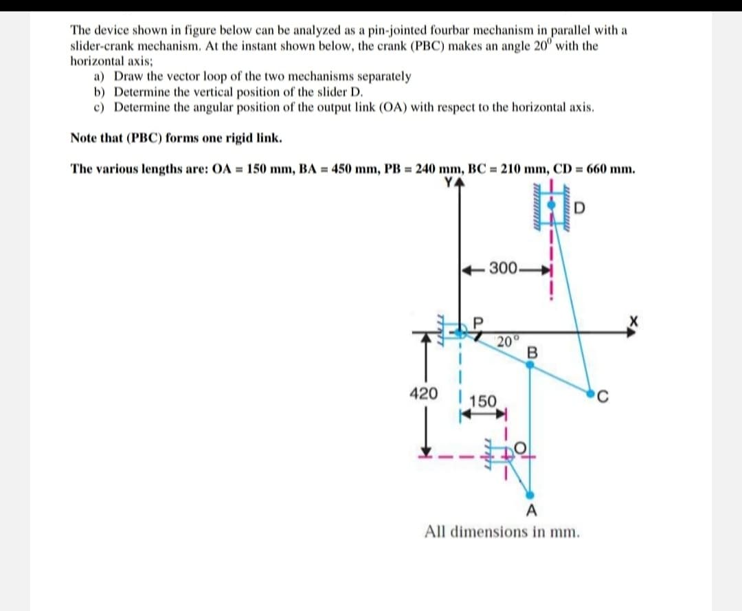
The device shown in figure below can be analyzed as a pin-jointed fourbar mechanism in parallel with a slider-crank mechanism. At the instant shown below, the crank (PBC) makes an angle 20° with the horizontal axis; a) Draw the vector loop of the two mechanisms separately b) Determine the vertical position of the slider D. c) Determine the angular position of the output link (OA) with respect to the horizontal axis. Note that (PBC) forms one rigid link. The various lengths are: OA = 150 mm, BA = 450 mm, PB = 240 mm, BC = 210 mm, CD = 660 mm. YA 300. P wwwwwwww D 20° B C 420 150 A All dimensions in mm.
The device shown in figure below can be analyzed as a pin-jointed fourbar mechanism in parallel with a slider-crank mechanism. At the instant shown below, the crank (PBC) makes an angle 20° with the horizontal axis; a) Draw the vector loop of the two mechanisms separately b) Determine the vertical position of the slider D. c) Determine the angular position of the output link (OA) with respect to the horizontal axis. Note that (PBC) forms one rigid link. The various lengths are: OA = 150 mm, BA = 450 mm, PB = 240 mm, BC = 210 mm, CD = 660 mm. YA 300. P wwwwwwww D 20° B C 420 150 A All dimensions in mm.

Elements Of Electromagnetics
7th Edition
ISBN:9780190698614
Author:Sadiku, Matthew N. O.
Publisher:Sadiku, Matthew N. O.
ChapterMA: Math Assessment
Section: Chapter Questions
Problem 1.1MA

Related questions

Question
Please veryyy urgent pls quickk (mechanical system) using rules
Transcribed Image Text:The device shown in figure below can be analyzed as a pin-jointed fourbar mechanism in parallel with a
slider-crank mechanism. At the instant shown below, the crank (PBC) makes an angle 20° with the
horizontal axis;
a) Draw the vector loop of the two mechanisms separately
b) Determine the vertical position of the slider D.
c) Determine the angular position of the output link (OA) with respect to the horizontal axis.
Note that (PBC) forms one rigid link.
The various lengths are: OA = 150 mm, BA = 450 mm, PB = 240 mm, BC = 210 mm, CD = 660 mm.
Y
300.
420
150
20°
B
D
A
All dimensions in mm.
Expert Solution
This question has been solved!
Explore an expertly crafted, step-by-step solution for a thorough understanding of key concepts.
Step 1: Determine vector loop, vertical position of slider D, angular position of output link (OA)
VIEWStep 2: Determine the vector loop of the two mechanisms separately
VIEWStep 3: Determine the vertical position of the slider D
VIEWStep 4: Determine the angular position of the output link (OA)
VIEWSolution
VIEW
Step by step
Solved in 5 steps with 27 images

Knowledge Booster


Learn more about
Need a deep-dive on the concept behind this application? Look no further. Learn more about this topic, mechanical-engineering and related others by exploring similar questions and additional content below.Recommended textbooks for you
Elements Of Electromagnetics
Mechanical Engineering
ISBN:
9780190698614
Author:
Sadiku, Matthew N. O.
Publisher:
Oxford University Press

Mechanics of Materials (10th Edition)
Mechanical Engineering
ISBN:
9780134319650
Author:
Russell C. Hibbeler
Publisher:
PEARSON

Thermodynamics: An Engineering Approach
Mechanical Engineering
ISBN:
9781259822674
Author:
Yunus A. Cengel Dr., Michael A. Boles
Publisher:
McGraw-Hill Education
Elements Of Electromagnetics
Mechanical Engineering
ISBN:
9780190698614
Author:
Sadiku, Matthew N. O.
Publisher:
Oxford University Press
Mechanics of Materials (10th Edition)
Mechanical Engineering
ISBN:
9780134319650
Author:
Russell C. Hibbeler
Publisher:
PEARSON
Thermodynamics: An Engineering Approach
Mechanical Engineering
ISBN:
9781259822674
Author:
Yunus A. Cengel Dr., Michael A. Boles
Publisher:
McGraw-Hill Education

Control Systems Engineering
Mechanical Engineering
ISBN:
9781118170519
Author:
Norman S. Nise
Publisher:
WILEY

Mechanics of Materials (MindTap Course List)
Mechanical Engineering
ISBN:
9781337093347
Author:
Barry J. Goodno, James M. Gere
Publisher:
Cengage Learning

Engineering Mechanics: Statics
Mechanical Engineering
ISBN:
9781118807330
Author:
James L. Meriam, L. G. Kraige, J. N. Bolton
Publisher:
WILEY