The diagram below shows a shaft with spur gear (B), bevel gear(D), and two supporting bearings (A and C). All dimensions are in millimeters and all shoulder fillets (at points where diameter changes) have a radius of 4.4 mm. The pressure angle for the spur gear at B is 16%. The pressure angle for the bevel gear at D is 18° and the bevel angle is 45°. Note that the shaft is designed so that only bearing A takes thrust. The shaft is made of steel with S,- 1060 MPa. All the critical surfaces are ground. The shaft rotates at 1820 rpm. A motor with a power of 650 kW is connected at the bevel gear through another bevel gear. This drives the shaft. A load is connected through another spur gear at the output spur gear at B. The standard deviation on the power is 60 kW. (a) Determine the forces acting on the gears. Recall that for a spur gear, the relation between the tangential component of the force and the radial component of the force and the pressure angle is given by F₁-F₁-tan(). For this bevel gear, the axial (thrust) component of the force on the gear and the radial component of the force on the gear will be related to the tangential component of the force on the gear and the pressure angle by F₁-F.-F. (b) Determine the 6 internal reaction forces at point E. (e) Calculate the equivalent mean and alternating stresses at E. (d) Assuming that a standard deviation on the fatigue strength that is 8% of the mean value, determine the failure rate for this design if the design is supposed to last for more than 10% cycles. Partial Answer The safety factor is Forces act at 500-mm dia. tan(6) √2 Forces act at 375-mm dia. SF2=1.42. 550- 120 dia. 650- E 450- Y 400 80 da 1)


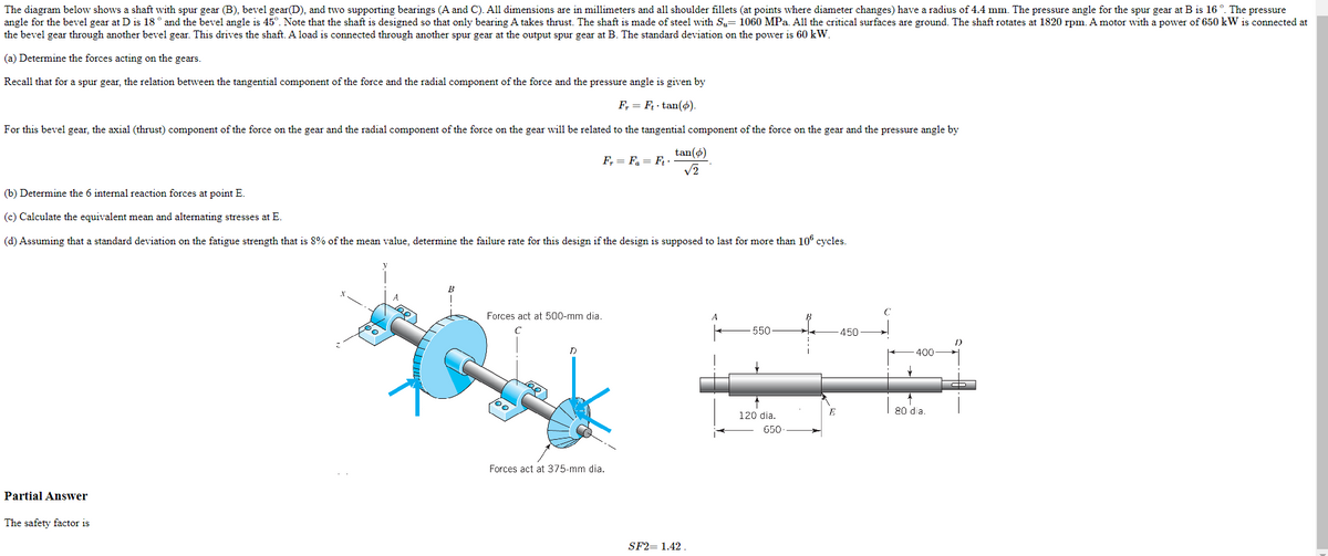
The diagram below shows a shaft with spur gear (B), bevel gear(D), and two supporting bearings (A and C). All dimensions are in millimeters and all shoulder fillets (at points where diameter changes) have a radius of . The pressure angle for the spur gear at B is . The pressure angle for the bevel gear at D is and the bevel angle is . Note that the shaft is designed so that only bearing A takes thrust. The shaft is made of steel with . All the critical surfaces are ground. The shaft rotates at . A motor with a power of is connected at the bevel gear through another bevel gear. This drives the shaft. A load is connected through another spur gear at the output spur gear at B. The standard deviation on the power is .
(a) Determine the forces acting on the gears.
Recall that for a spur gear, the relation between the tangential component of the force and the radial component of the force and the pressure angle is given by
.
For this bevel gear, the axial (thrust) component of the force on the gear and the radial component of the force on the gear will be related to the tangential component of the force on the gear and the pressure angle by
.
(b) Determine the 6 internal reaction forces at point E.
(c) Calculate the equivalent mean and alternating stresses at E.
(d) Assuming that a standard deviation on the fatigue strength that is 8% of the mean value, determine the failure rate for this design if the design is supposed to last for more than cycles.

Step by step
Solved in 5 steps with 27 images


