The end chord of a timber truss is framed into the bottom chord as shown in the figure (2) compute dimension b if the allowable shear stress is 40 MPa. (b) Determine dimension c so that the bearing stress does not exceed 25 MPa Use the last two digits of your ID Number for the missing force P KN 75 P = kN 30° -150 mm 30° ct
The end chord of a timber truss is framed into the bottom chord as shown in the figure (2) compute dimension b if the allowable shear stress is 40 MPa. (b) Determine dimension c so that the bearing stress does not exceed 25 MPa Use the last two digits of your ID Number for the missing force P KN 75 P = kN 30° -150 mm 30° ct

Mechanics of Materials (MindTap Course List)
9th Edition
ISBN:9781337093347
Author:Barry J. Goodno, James M. Gere
Publisher:Barry J. Goodno, James M. Gere
Chapter1: Tension, Compression, And Shear
Section: Chapter Questions
Problem 1.10.9P: A square steel tube of a length L = 20 ft and width b2= 10.0 in. is hoisted by a crane (see figure)....

Related questions
Question
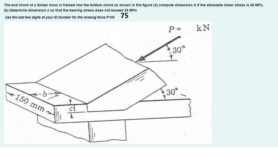
Transcribed Image Text:The end chord of a timber truss is framed into the bottom chord as shown in the figure (2) compute dimension b if the allowable shear stress is 40 MPa.
(b) Determine dimension c so that the bearing stress does not exceed 25 MPa
Use the last two digits of your ID Number for the missing force P KN
75
P =
kN
30°
-150 mm
30°
ct
Expert Solution
This question has been solved!
Explore an expertly crafted, step-by-step solution for a thorough understanding of key concepts.

Step by step
Solved in 2 steps with 2 images

Recommended textbooks for you
Mechanics of Materials (MindTap Course List)
Mechanical Engineering
ISBN:
9781337093347
Author:
Barry J. Goodno, James M. Gere
Publisher:
Cengage Learning
Mechanics of Materials (MindTap Course List)
Mechanical Engineering
ISBN:
9781337093347
Author:
Barry J. Goodno, James M. Gere
Publisher:
Cengage Learning