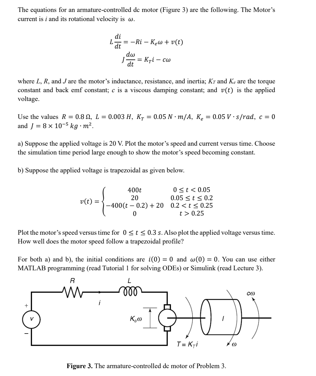
The equations for an armature-controlled de motor (Figure 3) are the following. The Motor's current is i and its rotational velocity is w. L where L, R, and J are the motor's inductance, resistance, and inertia; Kr and Ke are the torque constant and back emf constant; c is a viscous damping constant; and v(t) is the applied voltage. di = Use the values R = 0.8 N, L = 0.003 H, KT and J = 8 x 10⁻⁵ kg⋅m². v(t) = + -=-Ri - K₂w+v(t) dw J = K₁i - cw dt V dt a) Suppose the applied voltage is 20 V. Plot the motor's speed and current versus time. Choose the simulation time period large enough to show the motor's speed becoming constant. b) Suppose the applied voltage is trapezoidal as given below. i Plot the motor's speed versus time for 0 ≤ t ≤ 0.3 s. Also plot the applied voltage versus time. How well does the motor speed follow a trapezoidal profile? For both a) and b), the initial conditions are i(0) = 0 and w(0) = 0. You can use either MATLAB programming (read Tutorial 1 for solving ODEs) or Simulink (read Lecture 3). R 0.05 N·m/A, K₂ = 0.05 V s/rad, c = 0 400t 20 0 ≤ t < 0.05 0.05 ≤ t ≤ 0.2 -400(t - 0.2) +20 0.2 0.25 L m Kew ∙I T= Kri Figure 3. The armature-controlled de motor of Problem 3. *000
The equations for an armature-controlled de motor (Figure 3) are the following. The Motor's current is i and its rotational velocity is w. L where L, R, and J are the motor's inductance, resistance, and inertia; Kr and Ke are the torque constant and back emf constant; c is a viscous damping constant; and v(t) is the applied voltage. di = Use the values R = 0.8 N, L = 0.003 H, KT and J = 8 x 10⁻⁵ kg⋅m². v(t) = + -=-Ri - K₂w+v(t) dw J = K₁i - cw dt V dt a) Suppose the applied voltage is 20 V. Plot the motor's speed and current versus time. Choose the simulation time period large enough to show the motor's speed becoming constant. b) Suppose the applied voltage is trapezoidal as given below. i Plot the motor's speed versus time for 0 ≤ t ≤ 0.3 s. Also plot the applied voltage versus time. How well does the motor speed follow a trapezoidal profile? For both a) and b), the initial conditions are i(0) = 0 and w(0) = 0. You can use either MATLAB programming (read Tutorial 1 for solving ODEs) or Simulink (read Lecture 3). R 0.05 N·m/A, K₂ = 0.05 V s/rad, c = 0 400t 20 0 ≤ t < 0.05 0.05 ≤ t ≤ 0.2 -400(t - 0.2) +20 0.2 0.25 L m Kew ∙I T= Kri Figure 3. The armature-controlled de motor of Problem 3. *000

Introductory Circuit Analysis (13th Edition)
13th Edition
ISBN:9780133923605
Author:Robert L. Boylestad
Publisher:Robert L. Boylestad
Chapter1: Introduction
Section: Chapter Questions
Problem 1P: Visit your local library (at school or home) and describe the extent to which it provides literature...

Related questions
Question
100%
Transcribed Image Text:The equations for an armature-controlled dc motor (Figure 3) are the following. The Motor's
current is i and its rotational velocity is w.
L
+
di
where L, R, and Jare the motor's inductance, resistance, and inertia; Kō and Ke are the torque
constant and back emf constant; c is a viscous damping constant; and v(t) is the applied
voltage.
V
dt
Use the values R = 0.8 , L = 0.003 H, KT = 0.05 N·m/A, K₂ = 0.05 V s/rad, c = 0
and J = 8 x 10⁻⁵ kg. m².
20-{
v(t) =
= −Ri - Kew+v(t)
a) Suppose the applied voltage is 20 V. Plot the motor's speed and current versus time. Choose
the simulation time period large enough to show the motor's speed becoming constant.
b) Suppose the applied voltage is trapezoidal as given below.
R
M
dw
dt
i
= Kri - cw
Plot the motor's speed versus time for 0 ≤ t ≤ 0.3 s. Also plot the applied voltage versus time.
How well does the motor speed follow a trapezoidal profile?
For both a) and b), the initial conditions are i(0) = 0 and w(0) = 0. You can use either
MATLAB programming (read Tutorial 1 for solving ODEs) or Simulink (read Lecture 3).
400t
0 ≤ t < 0.05
0.05 ≤ t ≤ 0.2
20
−400(t – 0.2) +20 0.2 <t≤ 0.25
t> 0.25
0
L
mo
"I
K.w
T= Kri
Figure 3. The armature-controlled de motor of Problem 3.
(0)
CO
Expert Solution
This question has been solved!
Explore an expertly crafted, step-by-step solution for a thorough understanding of key concepts.

Step by step
Solved in 5 steps with 2 images

Knowledge Booster


Learn more about
Need a deep-dive on the concept behind this application? Look no further. Learn more about this topic, electrical-engineering and related others by exploring similar questions and additional content below.Recommended textbooks for you
Introductory Circuit Analysis (13th Edition)
Electrical Engineering
ISBN:
9780133923605
Author:
Robert L. Boylestad
Publisher:
PEARSON

Delmar's Standard Textbook Of Electricity
Electrical Engineering
ISBN:
9781337900348
Author:
Stephen L. Herman
Publisher:
Cengage Learning

Programmable Logic Controllers
Electrical Engineering
ISBN:
9780073373843
Author:
Frank D. Petruzella
Publisher:
McGraw-Hill Education
Introductory Circuit Analysis (13th Edition)
Electrical Engineering
ISBN:
9780133923605
Author:
Robert L. Boylestad
Publisher:
PEARSON
Delmar's Standard Textbook Of Electricity
Electrical Engineering
ISBN:
9781337900348
Author:
Stephen L. Herman
Publisher:
Cengage Learning
Programmable Logic Controllers
Electrical Engineering
ISBN:
9780073373843
Author:
Frank D. Petruzella
Publisher:
McGraw-Hill Education

Fundamentals of Electric Circuits
Electrical Engineering
ISBN:
9780078028229
Author:
Charles K Alexander, Matthew Sadiku
Publisher:
McGraw-Hill Education

Electric Circuits. (11th Edition)
Electrical Engineering
ISBN:
9780134746968
Author:
James W. Nilsson, Susan Riedel
Publisher:
PEARSON

Engineering Electromagnetics
Electrical Engineering
ISBN:
9780078028151
Author:
Hayt, William H. (william Hart), Jr, BUCK, John A.
Publisher:
Mcgraw-hill Education,