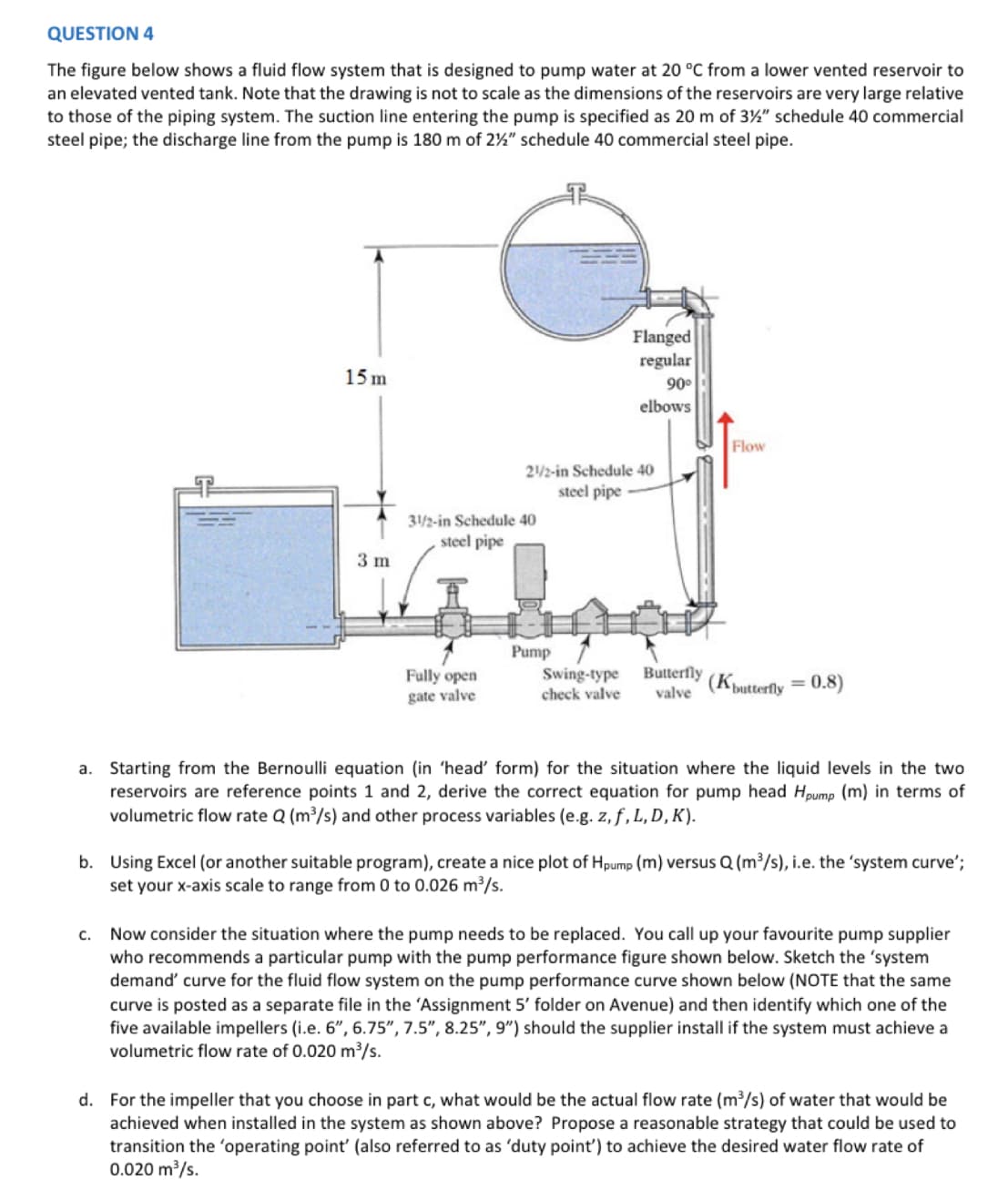
QUESTION 4 The figure below shows a fluid flow system that is designed to pump water at 20 °C from a lower vented reservoir to an elevated vented tank. Note that the drawing is not to scale as the dimensions of the reservoirs are very large relative to those of the piping system. The suction line entering the pump is specified as 20 m of 3½" schedule 40 commercial steel pipe; the discharge line from the pump is 180 m of 2%" schedule 40 commercial steel pipe. 15 m 3 m C. 31/2-in Schedule 40 steel pipe Fully open gate valve 21/2-in Schedule 40 steel pipe Flanged regular 90⁰ elbows Pump Flow Swing-type Butterfly check valve valve (butterfly = 0.8) a. Starting from the Bernoulli equation (in 'head' form) for the situation where the liquid levels in the two reservoirs are reference points 1 and 2, derive the correct equation for pump head Hpump (m) in terms of volumetric flow rate Q (m³/s) and other process variables (e.g. z, f, L, D, K). b. Using Excel (or another suitable program), create a nice plot of Hpump (m) versus Q (m³/s), i.e. the 'system curve'; set your x-axis scale to range from 0 to 0.026 m³/s. Now consider the situation where the pump needs to be replaced. You call up your favourite pump supplier who recommends a particular pump with the pump performance figure shown below. Sketch the 'system demand' curve for the fluid flow system on the pump performance curve shown below (NOTE that the same curve is posted as a separate file in the 'Assignment 5' folder on Avenue) and then identify which one of the five available impellers (i.e. 6", 6.75", 7.5", 8.25", 9") should the supplier install if the system must achieve a volumetric flow rate of 0.020 m³/s. d. For the impeller that you choose in part c, what would be the actual flow rate (m³/s) of water that would be achieved when installed in the system as shown above? Propose a reasonable strategy that could be used to transition the 'operating point' (also referred to as 'duty point') to achieve the desired water flow rate of
QUESTION 4 The figure below shows a fluid flow system that is designed to pump water at 20 °C from a lower vented reservoir to an elevated vented tank. Note that the drawing is not to scale as the dimensions of the reservoirs are very large relative to those of the piping system. The suction line entering the pump is specified as 20 m of 3½" schedule 40 commercial steel pipe; the discharge line from the pump is 180 m of 2%" schedule 40 commercial steel pipe. 15 m 3 m C. 31/2-in Schedule 40 steel pipe Fully open gate valve 21/2-in Schedule 40 steel pipe Flanged regular 90⁰ elbows Pump Flow Swing-type Butterfly check valve valve (butterfly = 0.8) a. Starting from the Bernoulli equation (in 'head' form) for the situation where the liquid levels in the two reservoirs are reference points 1 and 2, derive the correct equation for pump head Hpump (m) in terms of volumetric flow rate Q (m³/s) and other process variables (e.g. z, f, L, D, K). b. Using Excel (or another suitable program), create a nice plot of Hpump (m) versus Q (m³/s), i.e. the 'system curve'; set your x-axis scale to range from 0 to 0.026 m³/s. Now consider the situation where the pump needs to be replaced. You call up your favourite pump supplier who recommends a particular pump with the pump performance figure shown below. Sketch the 'system demand' curve for the fluid flow system on the pump performance curve shown below (NOTE that the same curve is posted as a separate file in the 'Assignment 5' folder on Avenue) and then identify which one of the five available impellers (i.e. 6", 6.75", 7.5", 8.25", 9") should the supplier install if the system must achieve a volumetric flow rate of 0.020 m³/s. d. For the impeller that you choose in part c, what would be the actual flow rate (m³/s) of water that would be achieved when installed in the system as shown above? Propose a reasonable strategy that could be used to transition the 'operating point' (also referred to as 'duty point') to achieve the desired water flow rate of

Elements Of Electromagnetics
7th Edition
ISBN:9780190698614
Author:Sadiku, Matthew N. O.
Publisher:Sadiku, Matthew N. O.
ChapterMA: Math Assessment
Section: Chapter Questions
Problem 1.1MA

Related questions
Question
Transcribed Image Text:Head-m
NPSHr-m
180
160
140
120
100
80
60
40
20
0
10
9 in
8.25 in
7.5 in
6.75 in
6 in
0.002
0.002
0.004
0.004
40
0.006
0.006
50
40
0.008
0.008
55
0.01
0.01
0.012
0.012
55
0.014
0.014
60
m³/s
0.016
0.016
60
65
0.018
0.018
0.02
0.02
68
0.022
0.022
0.024
0.024
50
60
0.026
0.026
Transcribed Image Text:QUESTION 4
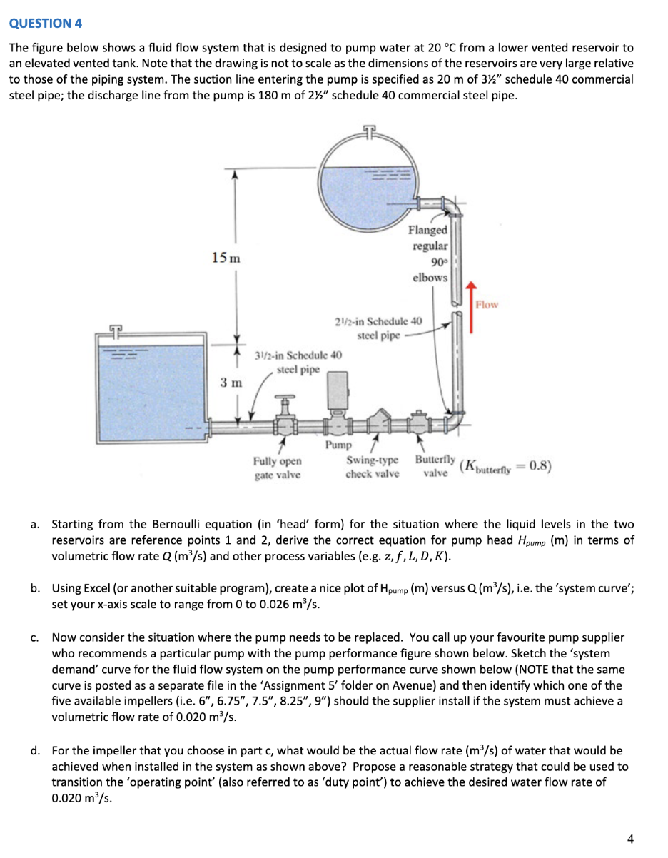
The figure below shows a fluid flow system that is designed to pump water at 20 °C from a lower vented reservoir to
an elevated vented tank. Note that the drawing is not to scale as the dimensions of the reservoirs are very large relative
to those of the piping system. The suction line entering the pump is specified as 20 m of 3½" schedule 40 commercial
steel pipe; the discharge line from the pump is 180 m of 2%" schedule 40 commercial steel pipe.
15 m
3 m
31/2-in Schedule 40
steel pipe
Fully open
gate valve
21/2-in Schedule 40
steel pipe
Flanged
regular
90⁰
elbows
Pump
Flow
Swing-type
check valve valve
Butterfly (K butterfly = 0.8)
a. Starting from the Bernoulli equation (in 'head' form) for the situation where the liquid levels in the two
reservoirs are reference points 1 and 2, derive the correct equation for pump head Hpump (m) in terms of
volumetric flow rate Q (m³/s) and other process variables (e.g. z, f, L, D, K).
b. Using Excel (or another suitable program), create a nice plot of Hpump (m) versus Q (m³/s), i.e. the 'system curve';
set your x-axis scale to range from 0 to 0.026 m³/s.
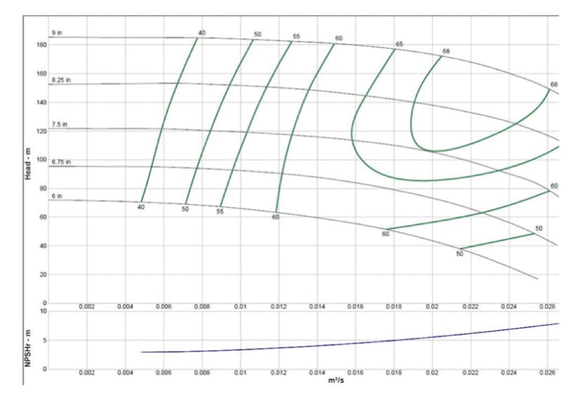
c. Now consider the situation where the pump needs to be replaced. You call up your favourite pump supplier
who recommends a particular pump with the pump performance figure shown below. Sketch the 'system
demand' curve for the fluid flow system on the pump performance curve shown below (NOTE that the same
curve is posted as a separate file in the 'Assignment 5' folder on Avenue) and then identify which one of the
five available impellers (i.e. 6", 6.75", 7.5", 8.25", 9") should the supplier install if the system must achieve a
volumetric flow rate of 0.020 m³/s.
d. For the impeller that you choose in part c, what would be the actual flow rate (m³/s) of water that would be
achieved when installed in the system as shown above? Propose a reasonable strategy that could be used to
transition the 'operating point' (also referred to as 'duty point') to achieve the desired water flow rate of
0.020 m³/s.
Expert Solution
This question has been solved!
Explore an expertly crafted, step-by-step solution for a thorough understanding of key concepts.

This is a popular solution!

Trending now
This is a popular solution!

Step by step
Solved in 2 steps with 2 images

Follow-up Questions
Read through expert solutions to related follow-up questions below.
Follow-up Question
Can you do Part D of this question. Parts A - C have already been done.
Transcribed Image Text:QUESTION 4
The figure below shows a fluid flow system that is designed to pump water at 20 °C from a lower vented reservoir to
an elevated vented tank. Note that the drawing is not to scale as the dimensions of the reservoirs are very large relative
to those of the piping system. The suction line entering the pump is specified as 20 m of 3½" schedule 40 commercial
steel pipe; the discharge line from the pump is 180 m of 2½" schedule 40 commercial steel pipe.
15 m
3 m
31/2-in Schedule 40
steel pipe
Fully open
gate valve
21/2-in Schedule 40
steel pipe
Pump
Flanged
regular
90⁰
elbows
Swing-type
check valve
Butterfly
valve
Flow
(Kbutterfly = 0.8)
a. Starting from the Bernoulli equation (in 'head' form) for the situation where the liquid levels in the two
reservoirs are reference points 1 and 2, derive the correct equation for pump head Hpump (m) in terms of
volumetric flow rate Q (m³/s) and other process variables (e.g. z, f, L, D,K).
b. Using Excel (or another suitable program), create a nice plot of Hpump (m) versus Q (m³/s), i.e. the 'system curve';
set your x-axis scale to range from 0 to 0.026 m³/s.
c. Now consider the situation where the pump needs to be replaced. You call up your favourite pump supplier
who recommends a particular pump with the pump performance figure shown below. Sketch the 'system
demand' curve for the fluid flow system on the pump performance curve shown below (NOTE that the same
curve is posted as a separate file in the 'Assignment 5' folder on Avenue) and then identify which one of the
five available impellers (i.e. 6", 6.75", 7.5", 8.25", 9") should the supplier install if the system must achieve a
volumetric flow rate of 0.020 m³/s.
d. For the impeller that you choose in part c, what would be the actual flow rate (m³/s) of water that would be
achieved when installed in the system as shown above? Propose a reasonable strategy that could be used to
transition the 'operating point' (also referred to as 'duty point') to achieve the desired water flow rate of
0.020 m³/s.
4
Solution
Knowledge Booster


Learn more about
Need a deep-dive on the concept behind this application? Look no further. Learn more about this topic, mechanical-engineering and related others by exploring similar questions and additional content below.Recommended textbooks for you
Elements Of Electromagnetics
Mechanical Engineering
ISBN:
9780190698614
Author:
Sadiku, Matthew N. O.
Publisher:
Oxford University Press

Mechanics of Materials (10th Edition)
Mechanical Engineering
ISBN:
9780134319650
Author:
Russell C. Hibbeler
Publisher:
PEARSON

Thermodynamics: An Engineering Approach
Mechanical Engineering
ISBN:
9781259822674
Author:
Yunus A. Cengel Dr., Michael A. Boles
Publisher:
McGraw-Hill Education
Elements Of Electromagnetics
Mechanical Engineering
ISBN:
9780190698614
Author:
Sadiku, Matthew N. O.
Publisher:
Oxford University Press
Mechanics of Materials (10th Edition)
Mechanical Engineering
ISBN:
9780134319650
Author:
Russell C. Hibbeler
Publisher:
PEARSON
Thermodynamics: An Engineering Approach
Mechanical Engineering
ISBN:
9781259822674
Author:
Yunus A. Cengel Dr., Michael A. Boles
Publisher:
McGraw-Hill Education

Control Systems Engineering
Mechanical Engineering
ISBN:
9781118170519
Author:
Norman S. Nise
Publisher:
WILEY

Mechanics of Materials (MindTap Course List)
Mechanical Engineering
ISBN:
9781337093347
Author:
Barry J. Goodno, James M. Gere
Publisher:
Cengage Learning

Engineering Mechanics: Statics
Mechanical Engineering
ISBN:
9781118807330
Author:
James L. Meriam, L. G. Kraige, J. N. Bolton
Publisher:
WILEY