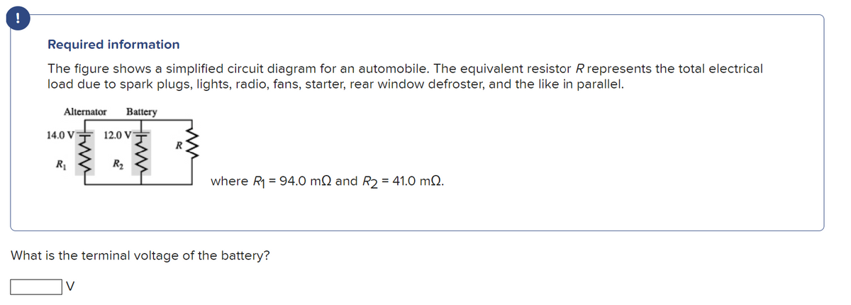
The figure shows a simplified circuit diagram for an automobile. The equivalent resistor R represents the total electrical load due to spark plugs, lights, radio, fans, starter, rear window defroster, and the like in parallel. Battery Alternator 14.0 VT R₁ 12.0 V R₂ HEM where R₁ = 94.0 m2 and R₂ = 41.0 m2.
Q: Hi , need help on Q4.2 ,4.3 , Q .A and Q .C ,pls assist , thanks
A:
Q: O For the circuit in Figure 2.3, convert both the voltage sources to current sources. (i) (ii)…
A: We need to find out the current and voltage for given circuit by source conversion and we need to…
Q: 6) In this experiment, students have utilized a long field coil (750mm, 484 turns/m), a short…
A: Given data Long field coil; Length of field coil : Lfield coil=750 mm Number of turns per unit…
Q: For the circuit below, determine the resistor current.The source is 6V, the Zener potential is 5V…
A:
Q: V₁ www Node 2 WW R₂ W Node 3 R₁ +4₁ , R3 = 3 2 and R4 = 4 . The circuit shown has V₁ = 5 V, I₁ = 2…
A:
Q: If the base current of a BJT is 250 μA and emitter current is 15 mA, then the common emitter current…
A: We need to find out the comman emitter current gain.
Q: 6. The four arms of a Wheatstone bridge have the following resistances in ohms. AB= 100, BC= 10,…
A: We need to find out the current through galvanometer for given circuit.
Q: 4. For the circuit below use a combination of Ohm's Law, KCL and KVL in order to compute the…
A:
Q: T(S)= (sta) (4) (S+4)(S)(S+1) • find the position error constant • find the velocity error constant…
A:
Q: Two single phase transformers with equal turns have impedance of (0.5+j0.3) ohms and (0.6+j10) ohms…
A:
Q: R₁ Vin M Vc +1 VA R3 ww VD R₂ M R4 VB ww
A: Given Data: A DC circuit with Resistors (R1 , R2 , R3 , and R4 ) DC supply (Vin) To Find: The…
Q: (a) For the circuit shown in Figure 3.1, determine the currents ls and l the resistance R. (1) (ii)…
A: “Since you have posted multiple questions with multiple sub parts,we will provide the solution only…
Q: A CIROVIT TAKES A CURRENT OF 3 A AT A POWER FACTOR OF 0.6 VAGGING WHEN $85-V, 50-H₂ SUPPLY. ANOTHER…
A: The given question deals with finding the current, power consumed and power factor of two circuits…
Q: 13. For the circuit shown in Fig. 2.181, determine current through R, when it takes values of 5 and…
A:
Q: 10k ww 50 mV 10k
A:
Q: In the circuit shown in the image below, if R₁ = 41 Q and R4 = 67 2, determine the current ₁ in A.…
A:
Q: the mesh-current method to find the branch currents 11, 12, and 13 he circuit in figure (Figure 1)…
A:
Q: Factor to obtain the product of sums for the following equations. Give answers in the number of…
A: a) f= AB+ AC'B+ DCB = AB( 1+C') + DCB = AB+ DCB b) f= ABC+ AB'C+ ACD+ BCD' =…
Q: a. What are the 3 types of Verilog modeling? b. Draw the equivalent circuit for given Verilog Code.…
A: (A) There are three main types of Verilog modeling: Data Flow modeling: This type of modeling…
Q: Need help on question A , B and C
A: For the given circuit we need to solve part A, B and C. In parallel branches voltage remain same.…
Q: Question 2 Calculate the current I in the circuit shown below at t = 3 sec 30V (+ t=0 18Ω eeeee 5Ω…
A:
Q: 14. Determine the nodal voltages for the networks in Fig. 17.72. 1₁ = 3A 20° HI. voo 50 40 20 (a)…
A: By applying nodal analysis to above circuits we get two linear equations interns of V1 and V2 for…
Q: Please explain motor drive system in electric vehicle.
A: A Motor Drive System is a combination of electrical and mechanical components used to control and…
Q: Problem 3: In the circuit below, the parameters for the JFET are Idss = 18 mA and Vgs(off) = - 3 V.…
A: The required parameters can be calculated by using the DC analysis of the amplifier circuit.
Q: The current (I) flowing in a circuit containing a capacitor that is discharging changes with time…
A:
Q: of a nhear system shown below, and the transient and ㅠ nput x(t) = 5sin(3t+ ). Assume the initial…
A:
Q: open-circuited terminals A and B to the circuits shown in Fig. 2.173. All resistances are in ohms.…
A:
Q: logic input 4.7 k www +5 V 470 AA
A:
Q: Figure Q.1(a) (b) Consider the circuit in Figure Q.1(b). Provided that; vsi(t)-20 sin(200t + 90°) V…
A:
Q: Ri Rf RL
A:
Q: Design the power supply using diode components. This power supply should have 2 outputs. 12 Vdc and…
A: i & iii ) The Block diagram regulated the power supply circuit The electronic design above…
Q: (b) Referring to the network in Figure 4.2, use nodal analysis to find the voltages Va and currents…
A: We need to find out the current and voltage for given circuit.
Q: 1. The control in flashlight circuit is a relay. True False
A: Introduction: Relay: An electrical relay is a device that switches or controls electrical circuits.…
Q: 3.) A 110 - KVA, 2200/110, GO He Has the pollowing cincuit constants: R₁ = 0.2252, R₂ = 0.5 mst. x₁…
A: Given information about a single phase transformer is written below. Rated kVA is S=110 kVA. Induced…
Q: 2) use Source bransformation to calcolate Io 6Ω www 5 A 352 ww SV 792 3 A 192 492 www
A: Introduction: Source transformation is the process of changing the form or structure of a source of…
Q: A) The MOSFET circuit of Figure 4A employs one of several methods of self-bias. Assume negligible…
A: MOSFET Circuit:
Q: Determine the total resistance RT in the circuit shown. Answer:| RT- 6 ΚΩ 54 ΚΩ , 2 ΚΩ 18 ΚΩ 3 ΚΩ 36…
A: Introduction Equivalent Resistance: The equivalent resistance is the resistance that represents the…
Q: Note: Suppose any suitable values that are not given to you. Given two time domain signals; x(t) and…
A: “Since you have posted a question with multiple sub-parts, we will solve the first three sub-parts…
Q: (b) For the circuit in Figure 4.2, the power dissipated in the resistor R₁ is 3 W, determine (0) the…
A: We need to find out the current and voltage for given circuit.
Q: 2. Use Thevenin's theorem to calculate the p.d. across terminals A and B in Fig. 2.171. www T6 V ww…
A: Introduction Thevenin's Theorem: Thevenin's Theorem is a theorem used in electrical engineering to…
Q: Need to help on 3 questions,pls assist thanks
A: Given: Two different circuits, To do: a) By transforming current source in voltage source in…
Q: A system is described by the following differential equation. dy(t) 8 +5y(t) + 32 = 4u(t) dt Where u…
A:
Q: The three-phase diode rectifier is fed from an AC source of 230 V, 60 Hz. The load is designed with…
A:
Q: (a) s²+2s +1' (b) 22. The input x and output y of a system are described by: $²+7s + 12' dy dx + 2y…
A:
Q: +V BB RB www Rc www =+V₂ CC
A: We need to find out the base current for given circuit.
Q: Write the equivalent resistance across terminals A and B. Answer: circuit reduction. 2 ΚΩ AO M RAB.…
A: Equivalent resistance is calculated by using reduction technique. Reduce the circuit from right side…
Q: Qy(6) for the circuit in figure Q4 (6) () Calculate I₁, I₂, V₁ and V₂ i) determine the dissipated 3A…
A:
Q: 2 x Vs ell Find Vs Is 1:17 ele 0.2 jo + 14 MVA 14.7KV10-7 lag 0.2 j0.1 pf Mill 8.2 jo.1 -
A:
Q: 1. Find the ammeter current in Fig. 2.57 by using loop analysis. Fig. 2.57 www Fig. 2.58 [1/7 A)…
A:
Q: What traits are present in unified communications systems? What are their advantages for the…
A: We need to explain What traits are present in unified communications systems? What are their…
Step by step
Solved in 3 steps with 1 images
- You are working as an electrician in a large steel manufacturing plant, and you are in the process of doing preventive maintenance on a large DC generator. You have megged both the series and shunt field windings and found that each has over 10 M to ground. Your ohmmeter, however, indicates a resistance of 1.5 across terminals S1andS2. The ohmmeter indicates a resistance of 225 between terminals F1andF2. Are these readings normal for this type machine, or is there a likely problem? Explain your answer.DEGREE: ELECTRICAL ENGINEERING SUBJECT/COURSE: INDUSTRIAL ELECTRONICSTOPIC: TRANSFORMERS NOTE: Please solve in this way. 1. Please have a good handwriting, some of the answers are not readable. Thank you!2. GIVEN. (Include symbols and units)3. ILLUSTRATION (Required).4. Step-by-step SOLUTION with Formulas and Symbols. No Shortcut, no skipping, and detailed as possible5. FINAL ANSWERS must be rounded up to two decimal places with corresponding unit. PROBLEM:The polarity test is performed upon a transformer. If the input voltage is Vin and the voltmeter readings are 121.8 volts (additive) and 110.2 volts (subtractive). Calculate the turns ration.DEGREE: ELECTRICAL ENGINEERING SUBJECT/COURSE: INDUSTRIAL ELECTRONICSTOPIC: TRANSFORMERS NOTE: Please solve in this way. 1. Please have a good handwriting, some of the answers are not readable. Thank you!2. GIVEN. (Include symbols and units)3. ILLUSTRATION (Required).4. Step-by-step SOLUTION with Formulas and Symbols. No Shortcut, no skipping, and detailed as possible5. FINAL ANSWERS must be rounded up to two decimal places with corresponding unit. PROBLEM:An 80:5 current transformer is connected to a 5-amp ammeter. if the latter reads 3.65 amp, what is the line current?
- DEGREE: ELECTRICAL ENGINEERING SUBJECT/COURSE: INDUSTRIAL ELECTRONICSTOPIC: TRANSFORMERS NOTE: Please solve in this way. 1. Please have a good handwriting, some of the answers are not readable. Thank you!2. GIVEN. (Include symbols and units)3. ILLUSTRATION (Required).4. Step-by-step SOLUTION with Formulas and Symbols. No Shortcut, no skipping, and detailed as possible5. FINAL ANSWERS must be rounded up to two decimal places with corresponding unit. PROBLEM:A 50:1 potential transformer is connected to a 150-volt voltmeter for the measurement of the high-side voltage of a distribution transformer. If the voltmeter deflection is 133, what is the transmission line voltage?answer the following questions using the attached picture. (c) To measure the current flow though R1 and the voltage onR5, how should we connect the ammeter and voltmeter?Draw a circuit diagram showing your answer. (d) What is the ideal impedance of1). an ammeter?2). a voltmeter?Subject: CircuitsShow your solution and circuits diagram
- DEGREE: ELECTRICAL ENGINEERING SUBJECT/COURSE: AC MACHINES NOTE: Please solve in this way. 1. Please have a good handwriting, some of the answers are not readable. Thank you!2. GIVEN. (Include symbols and units)3. REQUIRED/FIND/MISSING (with symbol/s and units)4. ILLUSTRATIONS such as diagrams and graphs are Required5. Step-by-step SOLUTION with Formulas and Symbols. No Shortcut, no skipping, and detailed as possible6. FINAL ANSWERS must be rounded up to two decimal places with corresponding unit. PROBLEM:A three phase converter has a rating of 600 kW when operating at unity power factor. Neglecting any change in efficiency, what would be its rating when operating at a power factor of 0.85.Basic Electrical Engineering You have been sent to a new home. The homeowner reports that sometimes the electric furnace trips the 240-V, 60-A circuit breaker connected to it. Upon examination, you find that the furnace contains three 5000-W heating elements designed to turn on in stages. For example, when the thermostat calls for heat, the first 5000-W unit turns on. After some period of time, the second unit will turn on, and then, after another time delay, the third unit will turn on. What do you think the problem is, and so would your recommendation for correcting? Explain your answer.DEGREE: ELECTRICAL ENGINEERING SUBJECT/COURSE: AC CIRCUITS NOTE: Please solve in this way. 1. Please have a good handwriting, some of the answers are not readable. Thank you! 2. GIVEN.(include symbols and units) 3. REQUIRED/FIND/MISSING (with symbol/s) 4. ILLUSTRATION (Required). 5. STEP-by-STEP SOLUTION with Formulas and Symbols. No Shortcut, No skipping, and detailed as possible 6. FINAL ANSWERS must be rounded up to three decimal places PROBLEM: • A star-connected load consists of three identical coils, each of inductance 159.2mH and resistance 50Ω. If the supply frequency is 50Hz and the line current is 3A determine: (a) the phase voltage and (b) the line voltage.