The flip-flops in the drawing below are positive edge triggered D flip-flops. Let Q2, Q1, QO = 0,0,0 initially. a) Plot the clock, Q2, Q1 and QO until the outputs begin to repeat. b) Show the circuits acts as a counter 00 D Q 1000 Hz/50% D Q
The flip-flops in the drawing below are positive edge triggered D flip-flops. Let Q2, Q1, QO = 0,0,0 initially. a) Plot the clock, Q2, Q1 and QO until the outputs begin to repeat. b) Show the circuits acts as a counter 00 D Q 1000 Hz/50% D Q

Chapter22: Sequence Control
Section: Chapter Questions
Problem 6SQ: Draw a symbol for a solid-state logic element AND.

Related questions

Question
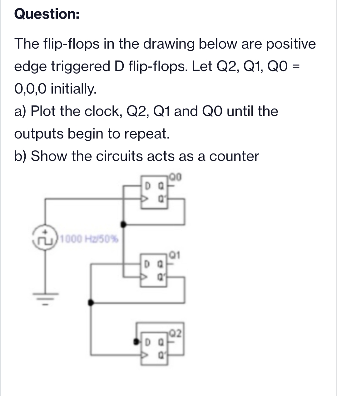
Transcribed Image Text:Question:
The flip-flops in the drawing below are positive
edge triggered D flip-flops. Let Q2, Q1, QO =
0,0,0 initially.
a) Plot the clock, Q2, Q1 and QO until the
outputs begin to repeat.
b) Show the circuits acts as a counter
00
1000 Hz/50%
Expert Solution
This question has been solved!
Explore an expertly crafted, step-by-step solution for a thorough understanding of key concepts.

This is a popular solution!

Trending now
This is a popular solution!

Step by step
Solved in 4 steps with 1 images

Knowledge Booster


Learn more about
Need a deep-dive on the concept behind this application? Look no further. Learn more about this topic, electrical-engineering and related others by exploring similar questions and additional content below.Recommended textbooks for you