The following shows the cross section and bending moment diagram of a two-bay continuous beam. The beam dimensions are 24" wide by 28" deep. Stirrups are #4. The maximum bending moments for the continuous beam are shown on the diagram. (Negative indicates tension at top and positive indicates tension at bottom). Determine the required effective depth, area of steel and number of top and bottom reinforcing bars using the sizes indicated.
The following shows the cross section and bending moment diagram of a two-bay continuous beam. The beam dimensions are 24" wide by 28" deep. Stirrups are #4. The maximum bending moments for the continuous beam are shown on the diagram. (Negative indicates tension at top and positive indicates tension at bottom). Determine the required effective depth, area of steel and number of top and bottom reinforcing bars using the sizes indicated.

Chapter2: Loads On Structures
Section: Chapter Questions
Problem 1P

Related questions
Question
The following shows the cross section and bending moment diagram of a two-bay continuous beam. The beam dimensions are 24" wide by 28" deep. Stirrups are #4.
The maximum bending moments for the continuous beam are shown on the diagram. (Negative indicates tension at top and positive indicates tension at bottom). Determine the required effective depth, area of steel and number of top and bottom reinforcing bars using the sizes indicated.
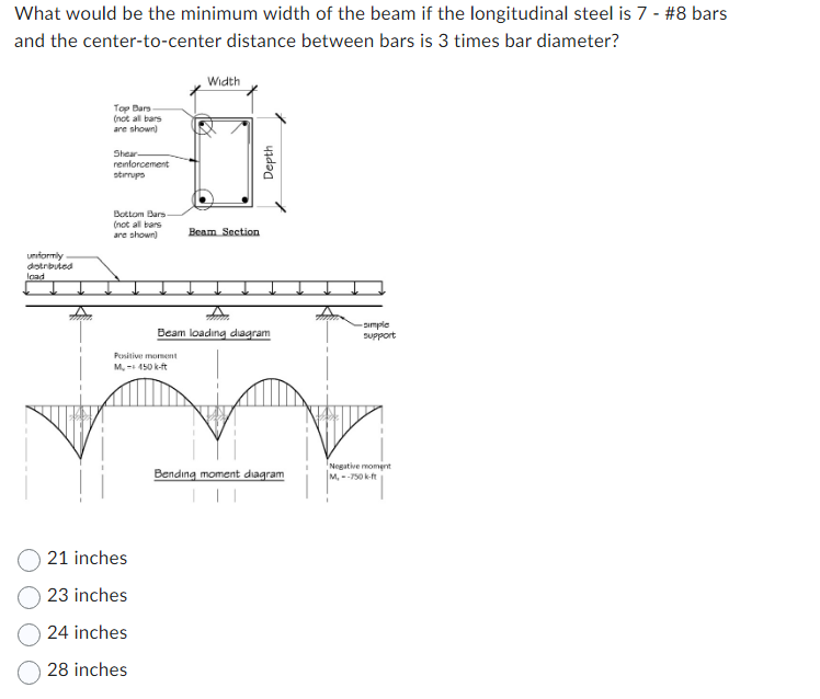
Transcribed Image Text:What would be the minimum width of the beam if the longitudinal steel is 7 - #8 bars
and the center-to-center distance between bars is 3 times bar diameter?
uniformly
distributed
load
Top Bars
(not all bars
are shown)
Shear-
reinforcement
stirrups
Bottom Bars-
(not all bars
are shown)
Positive moment
M, -+ 450 k-ft
21 inches
23 inches
24 inches
28 inches
Width
Beam Section
www
Depth
Beam loading diagram
Bending moment diagram
simple
support
Negative moment
M.--750 k-ft
Expert Solution
This question has been solved!
Explore an expertly crafted, step-by-step solution for a thorough understanding of key concepts.

Step by step
Solved in 2 steps with 1 images

Knowledge Booster


Learn more about
Need a deep-dive on the concept behind this application? Look no further. Learn more about this topic, civil-engineering and related others by exploring similar questions and additional content below.Recommended textbooks for you

Structural Analysis (10th Edition)
Civil Engineering
ISBN:
9780134610672
Author:
Russell C. Hibbeler
Publisher:
PEARSON

Principles of Foundation Engineering (MindTap Cou…
Civil Engineering
ISBN:
9781337705028
Author:
Braja M. Das, Nagaratnam Sivakugan
Publisher:
Cengage Learning
Structural Analysis (10th Edition)
Civil Engineering
ISBN:
9780134610672
Author:
Russell C. Hibbeler
Publisher:
PEARSON
Principles of Foundation Engineering (MindTap Cou…
Civil Engineering
ISBN:
9781337705028
Author:
Braja M. Das, Nagaratnam Sivakugan
Publisher:
Cengage Learning

Fundamentals of Structural Analysis
Civil Engineering
ISBN:
9780073398006
Author:
Kenneth M. Leet Emeritus, Chia-Ming Uang, Joel Lanning
Publisher:
McGraw-Hill Education


Traffic and Highway Engineering
Civil Engineering
ISBN:
9781305156241
Author:
Garber, Nicholas J.
Publisher:
Cengage Learning