The frame shown in Fig.1 is supported on a roller at A and pinned at C. For the loading indicated: i-Determine the support reactions, ii- Draw the axial load, shear force, and bending moment diagrams. 30 kN/m A 5 m B 20 kN/m 10 m 10 m RA Fig.1
The frame shown in Fig.1 is supported on a roller at A and pinned at C. For the loading indicated: i-Determine the support reactions, ii- Draw the axial load, shear force, and bending moment diagrams. 30 kN/m A 5 m B 20 kN/m 10 m 10 m RA Fig.1

Chapter9: Application Of Influence Lines
Section: Chapter Questions
Problem 11P

Related questions

Question
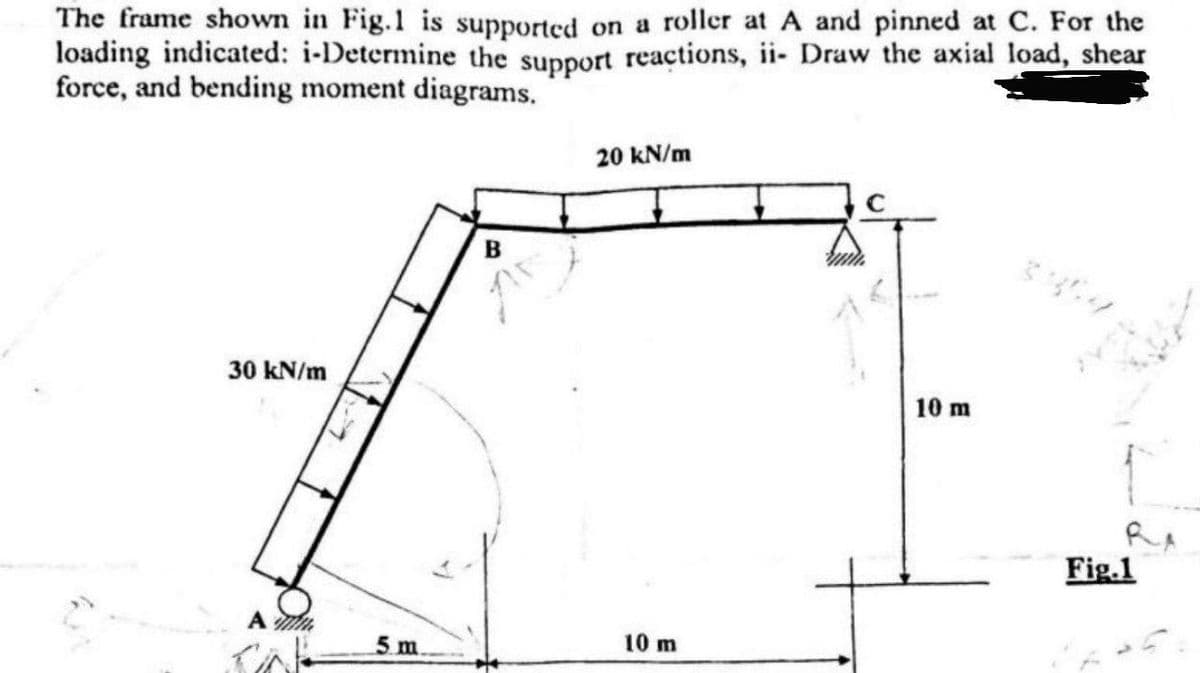
Transcribed Image Text:The frame shown in Fig.1 is supported on a roller at A and pinned at C. For the
loading indicated: i-Determine the support reactions, ii- Draw the axial load, shear
force, and bending moment diagrams.
30 kN/m
A
5 m.
B
20 kN/m
10 m
10 m
Fig.1
Expert Solution
This question has been solved!
Explore an expertly crafted, step-by-step solution for a thorough understanding of key concepts.

Step by step
Solved in 6 steps with 6 images

Knowledge Booster


Learn more about
Need a deep-dive on the concept behind this application? Look no further. Learn more about this topic, civil-engineering and related others by exploring similar questions and additional content below.Recommended textbooks for you