The next six questions pertain to the situation described below. A circuit is constructed with two capacitors and an inductor as shown. The values for the capacitors are: C = 112 µF and C2 = 271 µF. The inductance is L = 303 mH. At time t =0, the current through the inductor has its maximum value I (0) = 104 mA and it has the direction shown. a b C, C2 1) What is oo, the resonant frequency of this circuit? radians/s 2) What is Q1(t), the charge on the capacitor C1 at time t=t = 18 ms? The sign of Q1 is defined to be the sameas the sign of the potential difference Vah = Va - Vh at time t = tj. C 3) What is Vhe(t)= Vh - Ve, the voltage across the inductor at time t = 18 ms? Note that this voltage is a signed number. V 000
The next six questions pertain to the situation described below. A circuit is constructed with two capacitors and an inductor as shown. The values for the capacitors are: C = 112 µF and C2 = 271 µF. The inductance is L = 303 mH. At time t =0, the current through the inductor has its maximum value I (0) = 104 mA and it has the direction shown. a b C, C2 1) What is oo, the resonant frequency of this circuit? radians/s 2) What is Q1(t), the charge on the capacitor C1 at time t=t = 18 ms? The sign of Q1 is defined to be the sameas the sign of the potential difference Vah = Va - Vh at time t = tj. C 3) What is Vhe(t)= Vh - Ve, the voltage across the inductor at time t = 18 ms? Note that this voltage is a signed number. V 000

Introductory Circuit Analysis (13th Edition)
13th Edition
ISBN:9780133923605
Author:Robert L. Boylestad
Publisher:Robert L. Boylestad
Chapter1: Introduction
Section: Chapter Questions
Problem 1P: Visit your local library (at school or home) and describe the extent to which it provides literature...

Related questions

Question
Needed to be solved part 1,2 and 3 correclty in 20 minutes and get the thumbs up please show neat and clean work
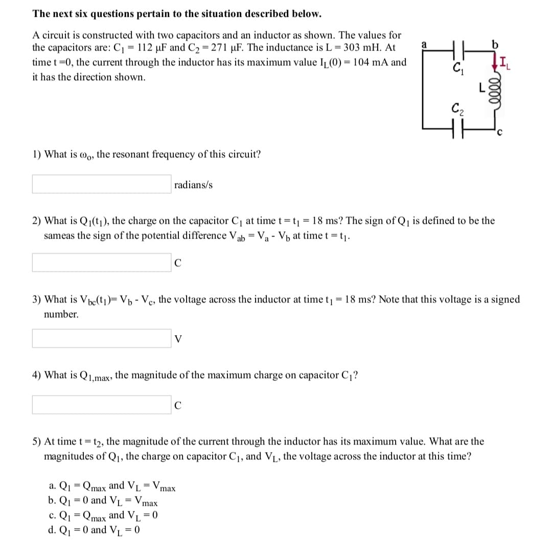
Transcribed Image Text:The next six questions pertain to the situation described below.
A circuit is constructed with two capacitors and an inductor as shown. The values for
the capacitors are: C = 112 µF and C2 = 271 µF. The inductance is L = 303 mH. At
a
b
time t =0, the current through the inductor has its maximum value Ij (0) = 104 mA and
it has the direction shown.
C2
1) What is wo, the resonant frequency of this circuit?
radians/s
2) What is Q1(t1), the charge on the capacitor C1 at time t= t = 18 ms? The sign of Q, is defined to be the
sameas the sign of the potential difference Vab = Va - Vb at time t = t1.
C
3) What is Vhe(t)= Vh - Ve, the voltage across the inductor at time t
= 18 ms? Note that this voltage is a signed
number.
V
4) What is Q1.max, the magnitude of the maximum charge on capacitor C1?
5) At time t= t2, the magnitude of the current through the inductor has its maximum value. What are the
magnitudes of Qj, the charge on capacitor C1, and VL, the voltage across the inductor at this time?
Qmax and VI = V,
b. Q1 = 0 and VL = Vm
а. Q
max
max
c. Q = Qmax and V = 0
d. Q = 0 and V = 0
Expert Solution
This question has been solved!
Explore an expertly crafted, step-by-step solution for a thorough understanding of key concepts.

Step by step
Solved in 4 steps with 4 images

Knowledge Booster


Learn more about
Need a deep-dive on the concept behind this application? Look no further. Learn more about this topic, electrical-engineering and related others by exploring similar questions and additional content below.Recommended textbooks for you
Introductory Circuit Analysis (13th Edition)
Electrical Engineering
ISBN:
9780133923605
Author:
Robert L. Boylestad
Publisher:
PEARSON

Delmar's Standard Textbook Of Electricity
Electrical Engineering
ISBN:
9781337900348
Author:
Stephen L. Herman
Publisher:
Cengage Learning

Programmable Logic Controllers
Electrical Engineering
ISBN:
9780073373843
Author:
Frank D. Petruzella
Publisher:
McGraw-Hill Education
Introductory Circuit Analysis (13th Edition)
Electrical Engineering
ISBN:
9780133923605
Author:
Robert L. Boylestad
Publisher:
PEARSON
Delmar's Standard Textbook Of Electricity
Electrical Engineering
ISBN:
9781337900348
Author:
Stephen L. Herman
Publisher:
Cengage Learning
Programmable Logic Controllers
Electrical Engineering
ISBN:
9780073373843
Author:
Frank D. Petruzella
Publisher:
McGraw-Hill Education

Fundamentals of Electric Circuits
Electrical Engineering
ISBN:
9780078028229
Author:
Charles K Alexander, Matthew Sadiku
Publisher:
McGraw-Hill Education

Electric Circuits. (11th Edition)
Electrical Engineering
ISBN:
9780134746968
Author:
James W. Nilsson, Susan Riedel
Publisher:
PEARSON

Engineering Electromagnetics
Electrical Engineering
ISBN:
9780078028151
Author:
Hayt, William H. (william Hart), Jr, BUCK, John A.
Publisher:
Mcgraw-hill Education,