*:The potential at point P due to Q1 and Q2 is Q, = 1x10⁻¹²C 0.5 m 0.5 m Q2 = 1x10-12C %3D %3D %3D 3D 50 cm 0.01271 V O 0.01797 V O -0.01271 V O ov O


Q: QI/ For the network shown in figure (Q1), the switch has been in position "a" for a long time. At…
A: In steady state, the inductor behaves as short circuit and the capacitor behaves as open circuit.…
Q: Problem 3 The following circuit is used by a biology student to study “frog kick." She noticed that…
A:
Q: In the figure, the capacitor is initially uncharged and R the switch (S) is closed at t = 0. (a)…
A: Transient Transient represent sudden change in the state of a network or circuit which are indicated…
Q: A circuit containing capacitors and inductors is shown in Figure Q1(a). Find the current I3. C =20µF…
A:
Q: In steady state, the two currents in the circuit are iL 2 mH A) ic = 0mA, i̟ = 2mA rell B) ic = 3mA,…
A: Given I =5 mA
Q: The circuit shown below is at dc steady state before the switch opens at t = 0. Find the voltage…
A:
Q: Q2/ For the network shown in figure (Q:), the switch has been open for a long time before closing at…
A: In circuit the sudden turn on and turn off of the switches causes the transient condition occurs.…
Q: The switch in the circuit seen in has been in position a for a long time. At the switch me…
A:
Q: *P3.24. Find the equivalent capacitance for each of the circuits shown in Figure P3.24 O. 2 μF 1 μF…
A:
Q: In the figure the capacitances are C, = 1.1 µF and C2 = 3.0 µF, and both capacitors are charged to a…
A: This probelm belongs to circuit theory . It is based on relationship in capacitor , voltage and…
Q: In the practice Charge and Discharge in RC Circuits you obtain the following graphs and fitted the…
A: For the RC charging circuit, the expression of the voltage is, v(t)=Vm1-e-tττ=Time…
Q: Convince yourself that the product of the resistance and capacitance is as shown: ne - - S Ẽ · dĽ\ /…
A:
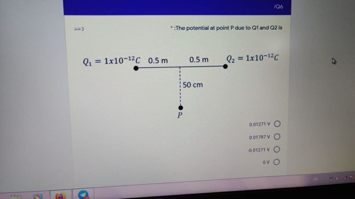
Q: :The potential at point P due to 01 and Q2 is Q1 1x10-12C 0.5 m 0.5 m Q2 = 1x10-12C %3D %3D 50 cm P
A: The data is Q1=1×10-12 C, Q2=1×10-12 C. Calculate the distance between Q1 and point P :…
Q: Q1/ For the network shown in figure (Q1), the switch has been in position "a" for a long time. At…
A: In this network shown as per given question, Initial switch at position a for long time. At the…
Q: Q1/ For the network shown in figure (Qi), the switch has been in position "a" for a long time. At…
A:
Q: а A Cz C3 C4 B CE C₁=C₂=C3 = 2 μF C4 = Cr² C6 - 4mF - TOTAL CAPACITANCE FROM ROINT AB? TOTAL ENERGY…
A:
Q: Q2/ For the network shown in figure (Q:), the switch has been open for a long time before closing at…
A: 2) The expression for the inductor current is found below: Before switching Switch was open then…
Q: After t=10τ seconds, we open switch S1 and close switch S2. Mark current time as t′=0. In this…
A: A capacitor reaches its steady state at t=5τ ,i.e a capacitor is nearly fully charged at t=5τ. And…
Q: Q2/ For the network shown in figure (Q:), the switch has been open for a long time before closing at…
A:
Q: Q2/ For the network shown in figure (Q:), the switch has been open for a long time before closing at…
A: Transient is a period of time a circuit takes in order to come back to the steady state condition…
Q: The ideal current source in the circuit of FigureP5.60 switches between various current levels,…
A: Refer to the diagram, it is known that the voltage across all the elements is the same. Now, write…
Q: 2. In this figure, assume arbitrary numbers for R1, R2, L1, and L2 including some number for the…
A:
Q: Untufastresult.com C ELECTRICAL AND ELECTRONICS ENGINEERING (BEEE) 1 Prove that the energy stored in…
A: Given, R = 25ΩL = 64 mHC = 80μFV = 110 ∠0°f = 50 Hz Circuit diagram,
Q: Switch S is closed in position a at time t = 0 for along of time in the below circuit, to being…
A: The capacitor stores the charge in the form of voltage. The current can be exponential decaying or…
Q: H4. Find the number of left, right and jw-axis poles in these following characteristic equations: I.…
A: Based on Routh-hurwitz table we can say the number of poles on right side ,left side, jw axis of a…
Q: The voltage across a 2-H inductance is shown in Figure P3.48. The initial current in theinductance…
A: The voltage across a 2-H inductance is shown in Figure P3.48 its expression is given by, Vt=10…
Q: Q2/ For the network shown in figure (Q2), the switch has been open for a long ti before closing at…
A:
Q: Ti (measured in A) - A t) 2. 3 7 8 9 This is a graph of the current in amperes (A) through a 1-nF…
A: In the above figure current waveform is shown. Current across an uncharged capacitor is drawn over a…
Q: 9Steady-state conditions exist in the circuit shown in Figure P5.27 for t 0.
A: For t < 0, write the expression for the current in the circuit. Write the value for the…
Q: 5) For the capacitor network shown In the figure below, C1-C2-D15 µF, C3=C4=10pF, C5=C6%3D5µF and…
A: In the circuit capacitor are connect in series and parallel combination C1=C2=15 µF, C3=C4=10uF,…
Q: A constant voltage of 10 V is applied to a 50-μH inductance, as shown in Figure P3.51. The current…
A: Voltage is given Current is changes from -100 A to 100 A Therefore, change in current is ;
Q: Find the equivalent capacitance Ceq seen by the terminals A and B in Figure A1 as a function of C…
A: The solution is
Q: Consider three charged capacitors connected as shown in the figure where CI-6 µF ,C2-2 µF, and C3=3…
A:
Q: The circuit shown in Figure P4.26 is operating in steady state. Determine the values of i L,v x ,and…
A: In steady-state capacitor acts as an open circuit and the inductor act as short circuit then the…
Q: "Given the potential function V = x²ytz+3), determine the electric potential at (3, 4, -6 -108 ml/C…
A: Find the electric potential at the point P
Q: In the circuit shown in Figure P4.7 let for - 00 <t< 0 for 0 st < 10 s v(t) = 20 -t for 10 <t< 20 s…
A: Given values are = Given circuit is =
Q: Find the voltage across the terminals of the capacitors in the circuit shown in the figure under dc…
A:
Q: (c) For the circuit in Figure Q1(c), under DC condition: (i) Determine the voltage across the…
A: In steady state capacitor acts as open circuit and inductor acts as short circuit. So, using kcl,…
Q: The switch in Figure Q2(c) has been in position a for a long time. At t = 0 s, the switch moves to…
A: Transient analysis
Q: For the circuit in Figure 3 the switch is in the left position for several minutes: (a) Find the…
A:
Q: In the figure R1 When the switch is opened after having been closed for a long time, the current in…
A: Given circuit is shown below. Given data is R1=4Ω, R2=1Ω. When switch is opened inductor current…
Q: Q2/ For the network shown in figure (Q:), the switch has been open for a long time before closing at…
A: Transient response is the response of a system which is the change in transient(equilibrium) or…
Q: 5. In the circuit shown in the figure, the switch S has been open for a long time and is suddenly…
A:
Q: The faces of the thin square plate in the below figure with side a = 21 are perfectly insulated. The…
A: we have given the following problem
Q: J1 J2 Xsc2 R1 4 Key = A 4700 Key = A Tektronix V1 =25 V C1 :1000µF R2 1kQ
A: If switch J2 is closed then C1 and R2 are in parallel. Now if J1 is closed then initially capacitor…
Q: ACTIVITY 4 LE CTRIC CIRCcUITS Direction: solve and analyze each of the following problem in 1. An…
A: The solution is given below
Q: QI/ For the network shown in figure (Q), the switch has been in position "a" for a long time. At…
A: In the network, the switch at position a for long time, then time t=0 ,the switch at move to…
Q: What is the current at t = 0.008 s? (In [A]) c) What is the voltage at t = 0.008 s?
A:
Q: Q2/ For the network shown in figure (Q:), the switch has been open for a long time before closing at…
A: Switch is opened for long time before t=0. When supply is DC, inductor is short circuited and…
Q: A parallel plate, capacitor with area of 15 m² , plates is 1mmFilled by two dielectri materiàl iwih…
A: This question is based on configuration of capacitors

Step by step
Solved in 3 steps with 2 images


- You are an electrician working in an industrial plant. You discover that the problem with a certain machine is a defective capacitor. The capacitor is connected to a 240-volt AC circuit. The information on the capacitor reveals that it has a capacitance value of 10 mF and a voltage rating of 240 VAC. The only 10-mF AC capacitor in the storeroom is marked with a voltage rating of 350 WVDC. Can this capacitor be used to replace the defective capacitor? Explain your answer.b) What is the current at t = 0.008 s? (In [A]) c) What is the voltage at t = 0.008 s? (in [V]) Hint: What relationships exist between voltage and current when the current in an inductor is interrupted?can you explain to me why the convolution of these two sinc fucntions which are rect functions equal a rect function? I thought when you convolute a rectangle and a rectangle with two different lengths, it makes a trapezoid shape. The answer says it is rectangle funtion so my code is corrcect but i dont understand why this is true. I need a step by step solution and explanation. here is the problem: Consider the signal x(t) = 2 sinc(6t + 3).the output y (t) = (x *h )(t) when x(t) ispassed through a filter with impulse response h (t) = 4sinc(2t -1). the matlab code was just to help me visuallize
- An emf source with E=100 V, a resistor with R=80 ohms, and a capacitance with C=4 uF are in series.connected. While the current is 0.9A during the loading of the capacitor, the load on the plates of the capacitor ishow big is it (in uC)?can you explain this? I know it has to do with parallel reasonance but why does the capacitor also have to get scaled? I know why the load does but not the capacitorCalculate for point P4, P5 and P6 only.
- For the capacitor network shown In the figure below, C1-C2-D15 µF, C3=C4=10pF, C5=C6%35µF and the applied potential is Vab 30 V. Calculate the charge on the capacitor C4=10 pF. Give your answer in microcoulombs.A 0.185H inductor is connected in series with a 99 Ohm resistor and an ac source. The voltage across the inductor is vL = -(11.5V)sin[(470rad/s)t]. Derive an expression for the voltage vR across the resistor. What is vR at 1.85 ms?a. Show how you would connect all five capacitors to get a maximum capacitance and find the maximum capacitance in terms of C. b. Show how you would connect all five capacitors to get a minimum capacitance and find the minimum capacitance in terms of C.
- how do i find the voltage of the capacitor? do i need to assume capacitor is charging so capacitor is open circuit and after that voltage on R2 is capacitor voltage after simplifying circuit?The current through a 220 μF capacitor is given below. Use Ohm’s Law to find the voltage. Convert to polar form, find the impedance and complete the math, then convert back to the waveform at i1 = 1.5sin(2500t + 30°) mA and i2 = 4.7sin(200t – 40°) mAhi. could you solve the question below? thank you.. A- Find the charge on the capacitor at t = 30 B- Find the voltage on the capacitor at t = 50 C- How much energy is stored in the capacitor by this current?