The steel bar has the original dimensions shown in the figure with b = 371 mm and c = 164 mm. If it is subjected to an axial load P = 44 kN, what is the change in its length? Est = 200 GPa. P 60 mm 20 mm 20 mm mm 50 mm P
The steel bar has the original dimensions shown in the figure with b = 371 mm and c = 164 mm. If it is subjected to an axial load P = 44 kN, what is the change in its length? Est = 200 GPa. P 60 mm 20 mm 20 mm mm 50 mm P

Mechanics of Materials (MindTap Course List)
9th Edition
ISBN:9781337093347
Author:Barry J. Goodno, James M. Gere
Publisher:Barry J. Goodno, James M. Gere
Chapter1: Tension, Compression, And Shear
Section: Chapter Questions
Problem 1.9.12P: What is the maximum possible value of the clamping Force C in the jaws of the pliers shown in the...

Related questions

Question
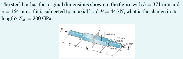
Transcribed Image Text:The steel bar has the original dimensions shown in the figure with b = 371 mm and
c = 164 mm. If it is subjected to an axial load P = 44 kN, what is the change in its
length? Est = 200 GPa.
P
60 mm
20 mm
20 mm
20 mm
P
0 mm
b
Expert Solution
This question has been solved!
Explore an expertly crafted, step-by-step solution for a thorough understanding of key concepts.

This is a popular solution!

Trending now
This is a popular solution!

Step by step
Solved in 2 steps with 2 images

Knowledge Booster


Learn more about
Need a deep-dive on the concept behind this application? Look no further. Learn more about this topic, mechanical-engineering and related others by exploring similar questions and additional content below.Recommended textbooks for you
Mechanics of Materials (MindTap Course List)
Mechanical Engineering
ISBN:
9781337093347
Author:
Barry J. Goodno, James M. Gere
Publisher:
Cengage Learning
Mechanics of Materials (MindTap Course List)
Mechanical Engineering
ISBN:
9781337093347
Author:
Barry J. Goodno, James M. Gere
Publisher:
Cengage Learning