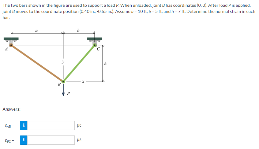
The two bars shown in the figure are used to support a load P. When unloaded, joint B has coordinates (0, 0). After load P is applied, joint B moves to the coordinate position (0.40 in., -0.65 in.). Assume a = 10 ft, b = 5 ft, and h = 7 ft. Determine the normal strain in each bar.
The two bars shown in the figure are used to support a load P. When unloaded, joint B has coordinates (0, 0). After load P is applied, joint B moves to the coordinate position (0.40 in., -0.65 in.). Assume a = 10 ft, b = 5 ft, and h = 7 ft. Determine the normal strain in each bar.

Mechanics of Materials (MindTap Course List)
9th Edition
ISBN:9781337093347
Author:Barry J. Goodno, James M. Gere
Publisher:Barry J. Goodno, James M. Gere
Chapter2: Axially Loaded Members
Section: Chapter Questions
Problem 2.7.6P: The truss ABC shown in the Figure is subjected to a horizontal load P at joint B. The two bars are...

Related questions
Question
Transcribed Image Text:The two bars shown in the figure are used to support a load P. When unloaded, joint B has coordinates (0,0). After load Pis applied,
joint B moves to the coordinate position (0.40 in., -0.65 in.). Assume a = 10 ft, b = 5 ft, and h = 7 ft. Determine the normal strain in each
bar.
a
b
h
B
P
Answers:
EAB=
EBC
Expert Solution
This question has been solved!
Explore an expertly crafted, step-by-step solution for a thorough understanding of key concepts.

Step by step
Solved in 2 steps with 1 images

Knowledge Booster


Learn more about
Need a deep-dive on the concept behind this application? Look no further. Learn more about this topic, mechanical-engineering and related others by exploring similar questions and additional content below.Recommended textbooks for you
Mechanics of Materials (MindTap Course List)
Mechanical Engineering
ISBN:
9781337093347
Author:
Barry J. Goodno, James M. Gere
Publisher:
Cengage Learning
Mechanics of Materials (MindTap Course List)
Mechanical Engineering
ISBN:
9781337093347
Author:
Barry J. Goodno, James M. Gere
Publisher:
Cengage Learning