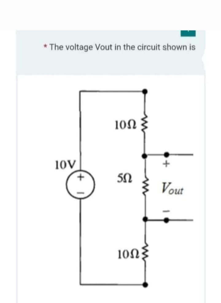
* The voltage Vout in the circuit shown is


Q: 2.14 Calculate the value of I in the circuit in Fig. P2.14. m
A:
Q: Consider a machine operating at synchronous speed under steady-state conditions, and let d.c. stator…
A: Given ia = 1 ; ib =- 1/2 ic = - 1/2 We have to find id , iq , io
Q: Your turn: Determine V3 employing voltage division 6 Volt + 5 102 202 + V3 +51 402 202 www + Sª V₂
A: We need to find out the voltage for given circuit by using of voltage division rule
Q: B) R₁= 20, R₂=402 resistors are connected in series and R, 120, R₁-49 resistors are connected in…
A:
Q: For a certain 12 V zener diode, a 10 mA change in zener current produces a 0.05 V change in zener…
A:
Q: Vs 12 V 47 kHz R₁ 1.2 ΚΩ 4 4.5 mH C₁ 0.001 μF What is the current through the capacitor in the given…
A: Solution !! Xc = 1/2*pi*f*C.
Q: Calculate the input voltage* (in millivolts) if the final output is 29.17 V. Vi=___mV *note…
A:
Q: A diode is an example of ___ switch. A. SPDT B. passive C. active D. DPDT
A: Diodes always have some barrier potential across it. It is represented by a drop of 0.7V or 0.3V…
Q: Problem 2: Find İLOAD through RLOAD using Thevenin's theorem 12 V + α www.xwww 3 Ω Μ 6Ω b 3 Ω 5Ω Μ…
A:
Q: A 3-phase 3-wire supply feeds a load consisting of three equal resistors connected in star. If one…
A: Given data, 3-phase 3-wire Supply:- Three-wire ac power circuits are used for three-phase power,…
Q: simple words, describe the clock generator.
A:
Q: 1 X L1 M1 M2 Y
A: Let two control block x and y connected in posiitive parallel then then resultant block will be x+y.…
Q: Calculate the current in the loop, 10 Ω 20 V 5Ω (+-) 10 V 80 V 20 Ω
A: The given circuit is,
Q: 3. Calculate the value of voltage in the circuit. = U=? 1=3 mA www R1 600 Ω
A: Given data, Circuit diagram is given as,
Q: determine the range of K to ensure stability. Problem #5 Repeat problem # 4 if G(s) K(s + 2) (s² +…
A:
Q: The RL circuit of the following figure is fed from a constant magnitude, variable frequency…
A: In this question we have given RL series circuit fed with variable frequency source....We have to…
Q: A four-pole DC shunt motor, 220 V, the number of conductors in the armature 1000, the typical…
A:
Q: For an n-channel JFET, VGs(om=-8V and Ipss=7 mA. Determine the value of VGs required to set up ID of…
A: Use drain current equation of jet to determine value of VGS.
Q: Example 2.9 The resistance of a long piece of copper wire is 48 2 at 20°C. a. What would the…
A: In this question, We need to determine the resistance at T(°C) We know Relation between resistance…
Q: A telephone signal with a cutoff frequency of 5 kHz is sampled at a rate 60 percent higher than the…
A: Cutt-off frequency f = 5 kHz We have to determine the sampling rate.
Q: B) For the lossless T.L shown below, the line is driven with a generator that has Eg=30Vrms and…
A:
Q: A 1.2-kW toaster takes roughly 4 minutes to heat four slices of bread. Find the cost of operating…
A:
Q: 7. The bode plot of a certain transfer function is given below. From the plot determine; Magnitude…
A: Phase cross frequency is the frequency at which the phase of the system becomes -180°. From the bode…
Q: Q1] for the following circuit choose the correct answer Assume that the circuit operates at @= 50…
A: Given: A network with various elements. To find: Input impedance, Zin Note: We'll use series and…
Q: Q4: (answer in phasor form) V = 10 cos 4t 552 www 0.1 F a) for the circuit shown bellow v=....... +…
A: impedance of capacitor Xc = 1j wc ohms . if Z1 and Z2 are connected in series with voltage source…
Q: Q1] for the following circuit choose the correct answer Assume that the circuit. operates at @= 50…
A:
Q: 2. If 750 μA is flowing through 11 kn of resistance, what is the voltage drop across the resistor?…
A: Given data: The current I=750 μA=750×10-6 A The resistance R=11kΩ=11000 Ω
Q: 4. Find the Total Resistance below. R₁ 15 Ω Γαλλί V₁: 100 V R₂ 30 Ω w R₂ 10 Ω = = A Μ B (a) R₁ 4 Ω R…
A:
Q: 4.33 Three single-phase, 10-kVA, 2400/120-V, 60-Hz transformers are connected to form a three-phase,…
A: We are authorized to answer one question at a time, since you have not mentioned which question you…
Q: (a) For the continuous time system whose differential equation representation is given as, d³y(t)…
A: The given differential equation is d3ytdt3+5d2ytdt2+9dytdt+16yt=5d2xtdt2+3dxtdt+8xt...(i) We need to…
Q: A 160 resistor, an 830 inductive reactance, and a 20 capacitive reactance are in series. A 120V 60Hz…
A:
Q: OBTAIN A NUMERICAL VALUE FOR THE POWER ABSORBED вч ЕАСH Егембит IN THE стешет вегоw. (SINGLE-L00P…
A:
Q: Problem 2: Find ¡LOAD through RLOAD using Thevenin's theorem 12 V α we kw Μ 3Ω 6Ω 3 Ω b 50 5Ω www…
A: Solution !!
Q: If the current i flowing in the straight conducting wire as shown in the figure decreases, find out…
A: Solution !! Solution From right hand rule, the magnetic field by the straight wire is directed into…
Q: A parallel R-C circuit containing 25 of resistance, and a capacitor of 95.5 μF, connected to a…
A: Resistance R = 25 Ω Capacitance C = 95.5 μF Voltage V = 200 V Frequency f = 50 Hz
Q: Determine the average power supplied to the circuit in Fig. 17.26 if i(t) = 2 + 10 cos(t+10°) + 6…
A: Given, Current, it=2+10cost+10°+6cos3t+35° A
Q: Problem 4: Find I, using Thevenin's or Norton's theorem 3Ω 4Ω ΖΩ 10 V (+1) Μ 6A 3Ω· (+1) 8V(+ 6Ω b…
A: Solution !!
Q: IN FIGARE BELOW (a) HOW MANY NODES ARE THERE? (b) HOW MANY BRANCHES ARE THERE? (C) IF WE MOVE FROM B…
A: Given- A circuit with no. of current source =2 No. of resistor = 5 To find- Number of nodes= ?…
Q: For the 13-kVA, 1540/220-V transformer shown in Figure (2): a) Calculate the full-load voltage…
A: Given, E1 = 1540 VE2 = 220 V Z1 = 4.4 + j6.5 ΩZ2 = 0.042 + j0.048 Ω Where, R1 = 4.4 ΩR2 = 0.042 Ω…
Q: to a 110V supply. At a temperature of 18°C, the current drawn is 0.575 A. After running the machine…
A:
Q: To get the best reading on a GPS, the device needs to locate: a. Three GPS satellites b. Seven GPS…
A: We need to select correct option for number of satellite for GPS .
Q: A feedback system root locus graph shown in figure below. For damped frequency 8.04 Hz, the gain K =…
A:
Q: 3. Normalized impedance of 1-j is: a) In the upper half of the impedance smith chart. b) In the…
A: Smith chart: Smith chart is a quick and easy way to determine the value of input resistance or…
Q: b) The reactance X of capacitance =jwc O True O False
A: reactance of capacitor X = 1j2πfc ohms . where , f is frequency . and c is capacitance in Farads .
Q: wo shunt generators and a battery are all connected to common bus-bars. The open circuit voltage of…
A: It is given that: VB=247 VEg1=Eg2=250 VRa1=Ra2=0.12 ΩRf1=Rf2=100 ΩIL=40 A
Q: For the op-amp shown in the following figure, the voltage gain is equal to------- Vino 3 ΚΩ 80 ΚΩ…
A: Circuit is given as:
Q: e) The phaser form of v=123cos(50t-30)= 123/-30
A:
Q: A heating element of a hot plate on an electric cooking range draws 24 amperes from 240 V mains. How…
A: Given data: Current, I=24 A Voltage, V=240 V mains. Time t is one hour and 15 minutes. Find:…
Q: 7. The bode plot of a certain transfer function is given below. From the plot determine; Magnitude…
A: SOLUTION From the bode plot determine the number of zeros of the…
Q: 1) DRAW A SCHEMATIC DIAGRAM FOR AUTOMATIC FORWARD & REVERSE MOTOR CONTROL USING LIMIT SWITCH, RELAY…
A: It is asked to draw a schematic diagram for an automatic forward and reverse motor control. We need…


Step by step
Solved in 2 steps with 1 images


- In the circuit given below, R = 130 kΩ. Find the voltage v0.Va = 30V, Vb = 45V, Ic = 12mA. The circuit is in dc steady state. Use superposition. Considering ONLY the contribution of the voltage source, Va . Determine V1. Enter your answer in V rounded to one decimal place.A series circuit of two pure elements has an applied voltage of 200sin(100t+30)V. Determine the resulting steady-state current of the two elements are:a) R = 300 L =2.5 Hb) R = 400, Xc= 150 c) R = 250, C = 100u d) R = 120, Xl=300
- 1.a. What circuit is shown on the image above? 1.b. What is the gain? 1.c. If R2 is 40x higher than R1 what will happen to node 2? Provide waveform and explain why it happens. 1.d. Modify the circuit to have an overall gain of 2. Provide photos.Write an expression for the output voltage vo(t) ofthe circuit shown if R1 = 1 k , R2 =2 k , R3 =47 k , v2(t)=(0.01 sin 3770t) V, andv1(t)=(0.04 sin 10000t)V. Write an expression forthe voltage appearing at the summing junction (v−).In the circuit given below, R = 40 Ω. Identify v(t) for t > 0. a) v(t) = 6 cos(0.5t) V b) v(t) = 12 cos(0.5t) V c) v(t) = 6 sin(0.5t) V d) v(t) = 3 sin(0.5t) V
- USE Current Divider Theorem. provide the tran func the input is V(s)a. output is 1 ohm resistorb. output is voltage acros inductorif you have answered this question pls do not reanswer, I just need confirmation. Va = 26V, Vb = 42V, Ic = 10mA. The circuit is in dc steady state. Use superposition. Considering ONLY the contribution of the voltage source, Va. Determine I3. Enter your answer in mA rounded to one decimal place.Find the value of R, so that R ab = 11Ω
- Q1 Find the Norton equivalent circuit for the following circuit with respect f0 the terminals ab using Multsim program with the values that are shown on the circuit M 25V 60 40 50 1ov RL 250 30A source voltage is connected across a 10ohm resistor. What is the la place transform of its currentExampleConsider the following electrical system as shown in the following figure. This circuit consistsof resistor, inductor and capacitor. All these electrical elements are connected in series. Theinput voltage applied to this circuit is vi and the voltage across the capacitor is the outputvoltage vo. Find vo/vi ?