Theory: No load Test of Three-phase Induction Motor The no load test is similar to the open circuit test on a transformer. It is performed to obtain the magnetizingbranch parameters (shunt parameters Rc and Xm) in the induction machine equivalent circuit. In this test, the motor is allowed to run with no-load at the rated voltage of rated frequency across its terminals. Machine will rotate at almost synchronous speed, which makes slip nearly equal to zero. This causes the equivalent rotor impedance to be very large (theoretically infinite neglecting the frictional and rotational losses). Therefore, the rotor equivalent impedance can be considered to be an open circuit which reduces the equivalent circuit diagram of the induction machine Fig. 1 (a) to the circuit as shown in Fig. 1 (d). Vph R1 jX lo > Ic Rc Ic Vph Rc ник чик lo R2' jx 2' Im R2" ((1-s)/s). jXm (a) lo R1+R2' j(X1+X2') www. Vph R1 R2' jX2' jX 1 lo ပ Ic Rc www (b) /lo Im jXm lo Im Ic Vph jXm Rc www Im E jXm (c) (d) Fig.1. Development of equivalent circuit of induction motor in open circuit test 1. Connect the circuit as shown in the connection diagram in Figure 2. 127v U 11 U A IM 127v > VLL1 V V No- Shaft 127v VLL2 W 12 W A Fig. 2. Induction motor open circuit test 2. Start the motor by ensuring the shaft is at no load condition. 3. For starting, increase the voltage to reach rated voltage. 4. Note the readings of voltmeter, ammeter and wattmeter by carefully and fill them in table 1 5. Reduce the voltage to zero and turn the main switch off. Table 1: The measured parameters during open circuit test of the induction motor Parameter Measurement Value VLL 240 IL P1 P2 Pinput Report 1. Draw the circuit diagram of open circuit test. Give some explanations 2. Calculate the machine parameters that is can be obtained from No-Load test (Rc and Xm). 3. What is the power factor of the machine? Comment on its value. 4. Comment on the slip of the machine in this case. 5. What are the different losses that are present in an induction machine in this case?
Theory: No load Test of Three-phase Induction Motor The no load test is similar to the open circuit test on a transformer. It is performed to obtain the magnetizingbranch parameters (shunt parameters Rc and Xm) in the induction machine equivalent circuit. In this test, the motor is allowed to run with no-load at the rated voltage of rated frequency across its terminals. Machine will rotate at almost synchronous speed, which makes slip nearly equal to zero. This causes the equivalent rotor impedance to be very large (theoretically infinite neglecting the frictional and rotational losses). Therefore, the rotor equivalent impedance can be considered to be an open circuit which reduces the equivalent circuit diagram of the induction machine Fig. 1 (a) to the circuit as shown in Fig. 1 (d). Vph R1 jX lo > Ic Rc Ic Vph Rc ник чик lo R2' jx 2' Im R2" ((1-s)/s). jXm (a) lo R1+R2' j(X1+X2') www. Vph R1 R2' jX2' jX 1 lo ပ Ic Rc www (b) /lo Im jXm lo Im Ic Vph jXm Rc www Im E jXm (c) (d) Fig.1. Development of equivalent circuit of induction motor in open circuit test 1. Connect the circuit as shown in the connection diagram in Figure 2. 127v U 11 U A IM 127v > VLL1 V V No- Shaft 127v VLL2 W 12 W A Fig. 2. Induction motor open circuit test 2. Start the motor by ensuring the shaft is at no load condition. 3. For starting, increase the voltage to reach rated voltage. 4. Note the readings of voltmeter, ammeter and wattmeter by carefully and fill them in table 1 5. Reduce the voltage to zero and turn the main switch off. Table 1: The measured parameters during open circuit test of the induction motor Parameter Measurement Value VLL 240 IL P1 P2 Pinput Report 1. Draw the circuit diagram of open circuit test. Give some explanations 2. Calculate the machine parameters that is can be obtained from No-Load test (Rc and Xm). 3. What is the power factor of the machine? Comment on its value. 4. Comment on the slip of the machine in this case. 5. What are the different losses that are present in an induction machine in this case?

Power System Analysis and Design (MindTap Course List)
6th Edition
ISBN:9781305632134
Author:J. Duncan Glover, Thomas Overbye, Mulukutla S. Sarma
Publisher:J. Duncan Glover, Thomas Overbye, Mulukutla S. Sarma
Chapter11: Transient Stability
Section: Chapter Questions
Problem 11.3P

Related questions
Question
VLL=240 IL=0.1 P1=19W P2=19W PINPUT=38W Please solve question 3 in report section
Transcribed Image Text:Theory:
No load Test of Three-phase Induction Motor
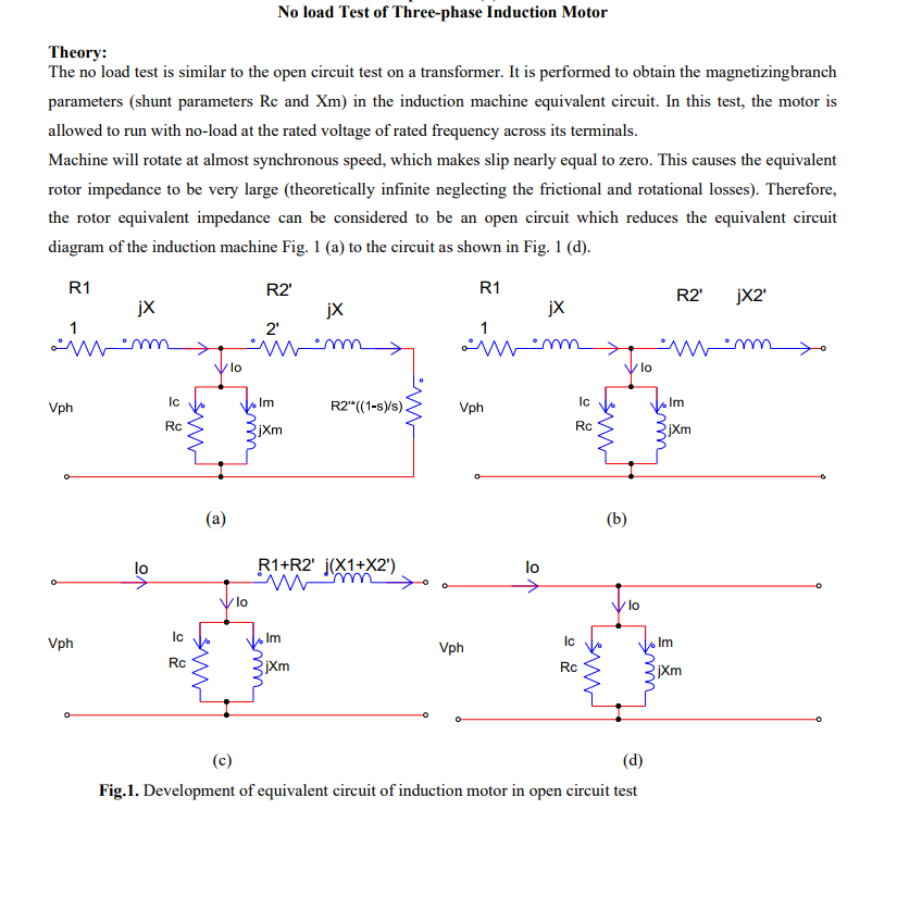
The no load test is similar to the open circuit test on a transformer. It is performed to obtain the magnetizingbranch
parameters (shunt parameters Rc and Xm) in the induction machine equivalent circuit. In this test, the motor is
allowed to run with no-load at the rated voltage of rated frequency across its terminals.
Machine will rotate at almost synchronous speed, which makes slip nearly equal to zero. This causes the equivalent
rotor impedance to be very large (theoretically infinite neglecting the frictional and rotational losses). Therefore,
the rotor equivalent impedance can be considered to be an open circuit which reduces the equivalent circuit
diagram of the induction machine Fig. 1 (a) to the circuit as shown in Fig. 1 (d).
Vph
R1
jX
lo
>
Ic
Rc
Ic
Vph
Rc
ник
чик
lo
R2'
jx
2'
Im
R2" ((1-s)/s).
jXm
(a)
lo
R1+R2' j(X1+X2')
www.
Vph
R1
R2' jX2'
jX
1
lo
ပ
Ic
Rc
www
(b)
/lo
Im
jXm
lo
Im
Ic
Vph
jXm
Rc
www
Im
E
jXm
(c)
(d)
Fig.1. Development of equivalent circuit of induction motor in open circuit test
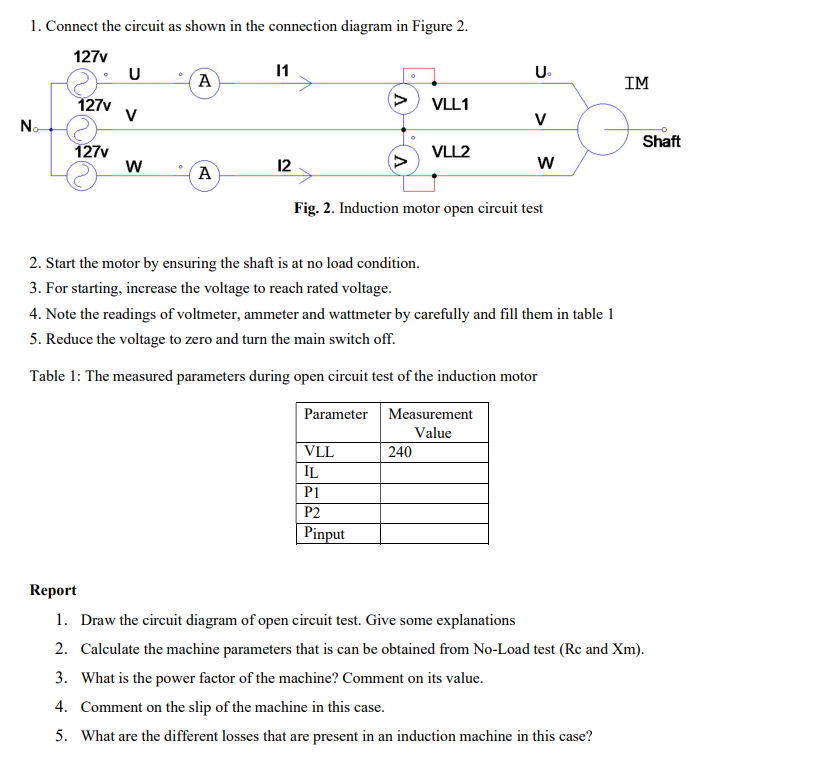
Transcribed Image Text:1. Connect the circuit as shown in the connection diagram in Figure 2.
127v
U
11
U
A
IM
127v
>
VLL1
V
V
No-
Shaft
127v
VLL2
W
12
W
A
Fig. 2. Induction motor open circuit test
2. Start the motor by ensuring the shaft is at no load condition.
3. For starting, increase the voltage to reach rated voltage.
4. Note the readings of voltmeter, ammeter and wattmeter by carefully and fill them in table 1
5. Reduce the voltage to zero and turn the main switch off.
Table 1: The measured parameters during open circuit test of the induction motor
Parameter
Measurement
Value
VLL
240
IL
P1
P2
Pinput
Report
1. Draw the circuit diagram of open circuit test. Give some explanations
2. Calculate the machine parameters that is can be obtained from No-Load test (Rc and Xm).
3. What is the power factor of the machine? Comment on its value.
4. Comment on the slip of the machine in this case.
5. What are the different losses that are present in an induction machine in this case?
Expert Solution
This question has been solved!
Explore an expertly crafted, step-by-step solution for a thorough understanding of key concepts.

Step by step
Solved in 2 steps with 1 images

Recommended textbooks for you
Power System Analysis and Design (MindTap Course …
Electrical Engineering
ISBN:
9781305632134
Author:
J. Duncan Glover, Thomas Overbye, Mulukutla S. Sarma
Publisher:
Cengage Learning
Power System Analysis and Design (MindTap Course …
Electrical Engineering
ISBN:
9781305632134
Author:
J. Duncan Glover, Thomas Overbye, Mulukutla S. Sarma
Publisher:
Cengage Learning