Three 10 Q resistors are in the circuit shown. The left end of the circuit is at a potential of 10 V, while the right end is at 0 V. a. What are the electric potentials at points 2 and 3 of the circuit? b. From the potential differences across each resistor, what are the currents in each resistor, including their directions (left or right)? c. What are the currents, including directions, in each wire? d. What is the equivalent resistance of this circuit measured between points 1 and 4? 10 V 4 OV wwwwvWw 10 N 10 N 10 N
Three 10 Q resistors are in the circuit shown. The left end of the circuit is at a potential of 10 V, while the right end is at 0 V. a. What are the electric potentials at points 2 and 3 of the circuit? b. From the potential differences across each resistor, what are the currents in each resistor, including their directions (left or right)? c. What are the currents, including directions, in each wire? d. What is the equivalent resistance of this circuit measured between points 1 and 4? 10 V 4 OV wwwwvWw 10 N 10 N 10 N

Principles of Physics: A Calculus-Based Text
5th Edition
ISBN:9781133104261
Author:Raymond A. Serway, John W. Jewett
Publisher:Raymond A. Serway, John W. Jewett
Chapter21: Current And Direct Current Circuits
Section: Chapter Questions
Problem 41P: Three 100- resistors are connected as shown in Figure P21.41 The maximum power that can safely be...

Related questions
Question
Hi there, please help me with answering this question, I am a bit confused here. It would be highly appreciated if all parts were answered clearly with explanation. Also, please read the question carefully because sometimes my questions are answered incorrectly and unfortunately I do not recieve a refund for it. Please answer with legible handwritting as well. Thank you very much. Thumbs up always given for correct answers! (:
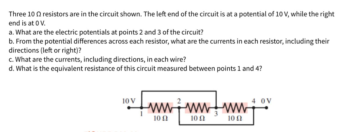
Transcribed Image Text:Three 10 Q resistors are in the circuit shown. The left end of the circuit is at a potential of 10 V, while the right
end is at 0 V.
a. What are the electric potentials at points 2 and 3 of the circuit?
b. From the potential differences across each resistor, what are the currents in each resistor, including their
directions (left or right)?
c. What are the currents, including directions, in each wire?
d. What is the equivalent resistance of this circuit measured between points 1 and 4?
10 V
4 0V
wwwwwW
10 Ω
10 Ω
10 Ω
Expert Solution
This question has been solved!
Explore an expertly crafted, step-by-step solution for a thorough understanding of key concepts.

This is a popular solution!

Trending now
This is a popular solution!

Step by step
Solved in 2 steps with 2 images

Knowledge Booster


Learn more about
Need a deep-dive on the concept behind this application? Look no further. Learn more about this topic, physics and related others by exploring similar questions and additional content below.Recommended textbooks for you
Principles of Physics: A Calculus-Based Text
Physics
ISBN:
9781133104261
Author:
Raymond A. Serway, John W. Jewett
Publisher:
Cengage Learning

Physics for Scientists and Engineers, Technology …
Physics
ISBN:
9781305116399
Author:
Raymond A. Serway, John W. Jewett
Publisher:
Cengage Learning

Physics for Scientists and Engineers with Modern …
Physics
ISBN:
9781337553292
Author:
Raymond A. Serway, John W. Jewett
Publisher:
Cengage Learning
Principles of Physics: A Calculus-Based Text
Physics
ISBN:
9781133104261
Author:
Raymond A. Serway, John W. Jewett
Publisher:
Cengage Learning
Physics for Scientists and Engineers, Technology …
Physics
ISBN:
9781305116399
Author:
Raymond A. Serway, John W. Jewett
Publisher:
Cengage Learning
Physics for Scientists and Engineers with Modern …
Physics
ISBN:
9781337553292
Author:
Raymond A. Serway, John W. Jewett
Publisher:
Cengage Learning

Physics for Scientists and Engineers
Physics
ISBN:
9781337553278
Author:
Raymond A. Serway, John W. Jewett
Publisher:
Cengage Learning

College Physics
Physics
ISBN:
9781938168000
Author:
Paul Peter Urone, Roger Hinrichs
Publisher:
OpenStax College
