
Videos
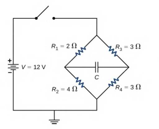
Consider the circuit below. The capacitor has a capacitance of 10 mF. The switch is closed and after a long time the capacitor is fully charged, (a) What is the current through each resistor a long time after the switch is closed? (b) What is the voltage across each resistor a long rime after the switch is closed? (c) What is the voltage across the capacitor a long time after the switch is closed? (d) What is the charge on the capacitor a long time after the switch is closed? (e) The switch is then opened. The capacitor discharges through the resistors. How long from the time before the current drops to one fifth of the initial value?

Trending nowThis is a popular solution!

Chapter 10 Solutions
University Physics Volume 2
Additional Science Textbook Solutions
Conceptual Integrated Science
College Physics (10th Edition)
College Physics: A Strategic Approach (4th Edition)
Tutorials in Introductory Physics
University Physics Volume 1
The Cosmic Perspective (8th Edition)


- Ralph has three resistors, R1, R2, and R3, connected in series. When connected to an ideal emf source E1, current I1 flows through the resistors. a. If the resistors are instead connected to a second source with E2=2E1, what is the new current through the resistors in terms of the first current? b. Show that, if each resistance is doubled and the resistors are connected in series to the second emf source, the current through the resistors is equal to I1.arrow_forwardA 160F capacitor charged to 450 V is dischargedthrough a 31.2k resistor, (a) Find the time constant.(b)Calculate the temperature increase of the resistor, given that its mass is 2.50 g and its specific heat is 1.67kJ/kg °C,noting that most of the thermal energy is retained in the short time of the discharge, (c) Calculate the new resistance, assuming it is pure carbon. (d) Does this change in resistance seem significant?arrow_forwardThe- pair of capacitors in Figure P28.63 are fully charged by a 12.0-V battery. The battery is disconnected, and the switch is then closed. Alter 1.00 ms has elapsed, (a) how much charge remains 011 the 3.00-F capacitor? (b) How much charge remains on the 2.00-F capacitor? (c) What is the current in the resistor at this time?arrow_forward
- A battery with an internal resistance of 10.0 produces an open circuit voltage of 12.0 V. A variable load resistance with a range from 0 to 30.0 is connected across the battery. (Note: A battery has a resistance that depends on the condition of its chemicals and that increases as the battery ages. This internal resistance can be represented in a simple circuit diagram as a resistor in series with the battery.) (a) Graph the power dissipated in the load resistor as a function of the load resistance. (b) With your graph, demonstrate the following important theorem: The power delivered to a load is a maximum if the load resistance equals the internal resistance of the source.arrow_forwardFigure P18.19 shows a Wheatstone bridge, a circuit used to precisely measure an unknown resistance R by varying Rvar until the ammeter reads zero current and the bridge is said to be balanced. If the bridge is balanced with Rvar = 9.00 , find (a) the value of the unknown resistance Rand (b) the current in the 1.00 resistor. (Hint: With the bridge balanced, the wire through the ammeter can effectively be removed from the circuit, leaving two pairs of resistors in parallel.) Figure Pl8.19arrow_forwardA capacitor with initial charge Q0 is connected across a resistor R at time t = 0. The separation between the plates of the capacitor changes as d = d0/(1 + t) for 0 t 1 s. Find an expression for the voltage drop across the capacitor as a function of time.arrow_forward
- Four resistors are connected to a battery as shown in Figure P21.40. The current in the battery is I, the battery emf is , and the resistor values are R1 = R, R2 = 2R, R3 = 4R, and R4 = 3R. (a) Rank the resistors according to the potential difference across them, from largest to smallest. Note any cases of equal potential differences. (b) Determine the potential difference across each resistor in terms of . (c) Rank the resistors according to the current in them, from largest to smallest. Note any cases of equal currents. (d) Determine the current in each resistor in terms of I. (e) If R3 is increased, what happens to the current in each of the resistors? (f) In the limit that R3 , what are the new values of the current in each resistor in terms of I, the original current in the battery? Figure P21.40arrow_forwardIn the circuit shown in Figure OQ21.15, each battery is delivering energy to the circuit by electrical transmission. All the resistors have equal resistance. (i) Rank the electric potentials at points a, b, c, d, and e from highest to lowest, noting any cases of equality in the ranking. (ii) Rank the magnitudes of the currents at the same points from greatest to least, noting any cases of equality.arrow_forwardConsider the circuit below. The battery has an emf of = 30.00 V and an internal resistance of r = 1,00 . (a) Find the equivalent resistance of the circuit and the current out of the battery. (b) Find the current through each resistor, (c) Find die potential drop across each resistor, (d) Find the power dissipated by each resistor, (e) Find the total power supplied by the batteries.arrow_forward
- In the circuit in the figure, a single-ring circuit consisting of a conductor with a resistance of 3MΩ and a capacitor with a capacitance of 1µF is fed by a battery with an emf of ε=4V.after t=1s;a) the current in the circuit,b) the energy (power) stored in the capacitor per unit time,c) the heat energy (power) spent on the resistor per unit time,d) find the power supplied by the battery and evaluate your result with your answers to options b and c.arrow_forwardThe circuit of the figure below shows a capacitor, two ideal batteries, two resistors, and a switch S. Initially S has been open for a long time. If it is then closed for a long time, what is the change in the charge on the capacitor? Assume C = 11 μF, ℰ1 = 1.0 V, ℰ2 = 5.0 V, R1 = 0.30 Ω, and R2 = 0.30 Ω. __________μC (please show the units when working through the problem so that I can follow it easier)arrow_forwardThe circuit of Figure shows a capacitor, two ideal batteries, two resistors, and a switch S. Initially S has been open for a long time. If it is then closed for a long time, what is the change in the charge on the capacitor?arrow_forward
 Physics for Scientists and Engineers: Foundations...PhysicsISBN:9781133939146Author:Katz, Debora M.Publisher:Cengage Learning
 Physics for Scientists and Engineers, Technology ...PhysicsISBN:9781305116399Author:Raymond A. Serway, John W. JewettPublisher:Cengage Learning
 Principles of Physics: A Calculus-Based TextPhysicsISBN:9781133104261Author:Raymond A. Serway, John W. JewettPublisher:Cengage Learning
 College PhysicsPhysicsISBN:9781285737027Author:Raymond A. Serway, Chris VuillePublisher:Cengage Learning
 College PhysicsPhysicsISBN:9781305952300Author:Raymond A. Serway, Chris VuillePublisher:Cengage Learning