Using the coordinate axes shown, write equations for the shear V and bending moment M for any section In the interval 10 ft sxs 20 ft of the beam shown in Fig. 1500 Ib 250 Ib/ft 11000 ft-lb 10 ft-
Using the coordinate axes shown, write equations for the shear V and bending moment M for any section In the interval 10 ft sxs 20 ft of the beam shown in Fig. 1500 Ib 250 Ib/ft 11000 ft-lb 10 ft-

International Edition---engineering Mechanics: Statics, 4th Edition
4th Edition
ISBN:9781305501607
Author:Andrew Pytel And Jaan Kiusalaas
Publisher:Andrew Pytel And Jaan Kiusalaas
Chapter9: Moments And Products Of Inertia Of Areas
Section: Chapter Questions
Problem 9.16P: Figure (a) shows the cross-sectional dimensions for the structural steel section known as C1020...

Related questions
Question
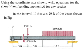
Transcribed Image Text:Using the coordinate axes shown, write equations for the
shear V and bending moment M for any section
In the interval 10 ft sxs 20 ft of the beam shown
in Fig.
1500 Ib
250 Ib/ft
11000 ft-lb
10 ft-
Expert Solution
This question has been solved!
Explore an expertly crafted, step-by-step solution for a thorough understanding of key concepts.

This is a popular solution!

Trending now
This is a popular solution!

Step by step
Solved in 2 steps with 1 images

Recommended textbooks for you
International Edition---engineering Mechanics: St…
Mechanical Engineering
ISBN:
9781305501607
Author:
Andrew Pytel And Jaan Kiusalaas
Publisher:
CENGAGE L
International Edition---engineering Mechanics: St…
Mechanical Engineering
ISBN:
9781305501607
Author:
Andrew Pytel And Jaan Kiusalaas
Publisher:
CENGAGE L