V10- U20- R₁ ww R₂ R3 ww + U₁ Figure 1: Circuit for Laboratory Experiment 4 1. Derive the expression of v, in terms of U₁, U2, R1, R2 and R3, in Figure 1. 0%
V10- U20- R₁ ww R₂ R3 ww + U₁ Figure 1: Circuit for Laboratory Experiment 4 1. Derive the expression of v, in terms of U₁, U2, R1, R2 and R3, in Figure 1. 0%

Introductory Circuit Analysis (13th Edition)
13th Edition
ISBN:9780133923605
Author:Robert L. Boylestad
Publisher:Robert L. Boylestad
Chapter1: Introduction
Section: Chapter Questions
Problem 1P: Visit your local library (at school or home) and describe the extent to which it provides literature...

Related questions

Question
Transcribed Image Text:V10-
U2 0
R₁
www
R₂
M
R3
ww
+
U₁
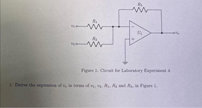
Figure 1: Circuit for Laboratory Experiment 4
1. Derive the expression of v, in terms of U₁, V2, R₁, R2 and R3, in Figure 1.
-0%
![2. Substitute the resistor values R₁ = R₂ = 1 kf and R3 = 10 kf? to the expression you found in Question 1. Comment on
the operation of the circuit in Figure 1.
3. Build the circuit in Figure 1 using V+ = 12V and V_=-12 V, and the resistances as indicated in Question 2. The
operational amplifier, U₁, is LM741. Check the pinout of LM741 when necessary. The input voltages are:
V₁ = 100 cos(2*200t) [mV]
U2 = 200 cos(2100t) [mV]
Observe the output, vo, on an oscilloscope and comment on the behavior.](/v2/_next/image?url=https%3A%2F%2Fcontent.bartleby.com%2Fqna-images%2Fquestion%2F59f2532e-227d-4b46-8fc6-c1ec59e2a9af%2F5fb50cac-af6a-4578-9d18-460b2395ac6f%2Fo9thww4_processed.jpeg&w=3840&q=75)
Transcribed Image Text:2. Substitute the resistor values R₁ = R₂ = 1 kf and R3 = 10 kf? to the expression you found in Question 1. Comment on
the operation of the circuit in Figure 1.
3. Build the circuit in Figure 1 using V+ = 12V and V_=-12 V, and the resistances as indicated in Question 2. The
operational amplifier, U₁, is LM741. Check the pinout of LM741 when necessary. The input voltages are:
V₁ = 100 cos(2*200t) [mV]
U2 = 200 cos(2100t) [mV]
Observe the output, vo, on an oscilloscope and comment on the behavior.
Expert Solution
This question has been solved!
Explore an expertly crafted, step-by-step solution for a thorough understanding of key concepts.

Step by step
Solved in 2 steps with 1 images

Knowledge Booster


Learn more about
Need a deep-dive on the concept behind this application? Look no further. Learn more about this topic, electrical-engineering and related others by exploring similar questions and additional content below.Recommended textbooks for you
Introductory Circuit Analysis (13th Edition)
Electrical Engineering
ISBN:
9780133923605
Author:
Robert L. Boylestad
Publisher:
PEARSON

Delmar's Standard Textbook Of Electricity
Electrical Engineering
ISBN:
9781337900348
Author:
Stephen L. Herman
Publisher:
Cengage Learning

Programmable Logic Controllers
Electrical Engineering
ISBN:
9780073373843
Author:
Frank D. Petruzella
Publisher:
McGraw-Hill Education
Introductory Circuit Analysis (13th Edition)
Electrical Engineering
ISBN:
9780133923605
Author:
Robert L. Boylestad
Publisher:
PEARSON
Delmar's Standard Textbook Of Electricity
Electrical Engineering
ISBN:
9781337900348
Author:
Stephen L. Herman
Publisher:
Cengage Learning
Programmable Logic Controllers
Electrical Engineering
ISBN:
9780073373843
Author:
Frank D. Petruzella
Publisher:
McGraw-Hill Education

Fundamentals of Electric Circuits
Electrical Engineering
ISBN:
9780078028229
Author:
Charles K Alexander, Matthew Sadiku
Publisher:
McGraw-Hill Education

Electric Circuits. (11th Edition)
Electrical Engineering
ISBN:
9780134746968
Author:
James W. Nilsson, Susan Riedel
Publisher:
PEARSON

Engineering Electromagnetics
Electrical Engineering
ISBN:
9780078028151
Author:
Hayt, William H. (william Hart), Jr, BUCK, John A.
Publisher:
Mcgraw-hill Education,