Voo Rp Zin Cr Vout Rs VinO HEM.


Q: What is the difference between Signal to noise (S/N) &and Signal Pluse Noise To Noise
A: Signal-to-noise ratio (SNR or S/N) It is an action utilized in science and designing that looks at…
Q: The frequency response of circuit below R1 V¡ o OV C1 O a. Lowpass filter. а. O b. Bandpass filter.…
A:
Q: The circuit shown in figure is in series resonance at frequency fc Hz. The value of Vc in volts is…
A:
Q: 8. (a) An angle modulated signal with carrier frequency w. = 2a x10° rad/sec is given as follow :…
A: The solution can be achieved as follows.
Q: 3.3 Specify the Nyquist rate and the Nyquist interval for each of the following signals: (a) g(t) =…
A:
Q: C Vi R Vo Figure 3 The circuit given in Figure 3 H(jw) = V obtaining the transfer function frequency…
A: We have to find trasnfer function
Q: Determine Vce in the given circuit if VBB = 10V, VCC = 15V, RB = 10k and RC = 100 Q. Assume ß = 100…
A:
Q: A parrallel resonant R= 5Kr, L=8mH, C=60UF Determine: The resonant Feeguency The band wid th Circuit…
A: The resonance is the point at which the response of the circuit will be maximum. At resonance the…
Q: I want the answer in detail and as quickly as possible please Q/ Using capacitors and resistors,…
A:
Q: frequency of resonance.
A: Resonant frequency
Q: The circuit shown in figure is in series resonance at frequency fc Hz. The value of Vc in volts is…
A:
Q: The circuit shown in figure is in series resonance at frequency fc Hz. The value of Vc in volts is…
A: Given- R=10 Ω,L=0.1 H,C=0.1 μF. To Find- It is needed to find the value of Vc in volts.
Q: The signal can be reconstructed Above Nyquist rate O At & above the Nyquist rate O None of the…
A: Nyquist rate is equal to the twice the maximum frequency of the signal. It is given by fn = 2fm
Q: The circuit shown in figure is in series resonance at frequency fc Hz. The value of Vc in volts is…
A:
Q: Q5) A certain unity feedback system is given by G(s)=2000(s+0.5)/[s(s+10)(s+50)] Draw the Bode plot…
A: A bode plot has two plots: (i) Magnitude plot (ii) Phase plot The magnitude of bode plot is between…
Q: SUPPOSE A CIRCUIT HAS A TRANSFER FUNCTION OF jw THE FORM A (w)= Ao (1- ). FOR Ao-10 Vlv ANC Wo Wo:…
A: In this question we will find phase and gain..
Q: Draw bode plof and determine gain margin and phase margin G(s)H(s) aa 720(st125) G10)(+2+9)
A: The bode plot of the system will be plotted as:-
Q: Identify, which type of harmonics is minimized by resonant converter? O a. Zero frequency harmonics…
A: Choose the correct option Which type of harmonics is minimized by the resonant converter.
Q: Consider a system G(s) in a unity feedback setting, with a bode plot as shown in figure below: 250…
A: Given: Brief description: In the given question they want to know whether the given system is…
Q: Design a differentiator circuit to differentiate signals with frequencies up to 150 Hz and produces…
A: It is given that: Vo=10 V at F=150HzVi=10 V at F=50kHzC=0.01μF
Q: Magnitude (dB) Phase (deg) 20 10 0 -10 <-20 -30 40 0 -45 -90 -135 -100 Bode Diagram 10° Frequency…
A: Phase cross over frequency: The frequency at which phase plot touches the -180° axis. From the phase…
Q: Design a series resonant circuit with an input voltage of 5 V 20° to have the following…
A: Given that Vin=5∠0° VoltIp=500 mAIrms=5002 mAB=120 Hzfr=8400 Hz Fig:…
Q: *9. Design a series resonant circuit with an input voltage of 5 V 20° to have the following…
A: We need to find out the value of resistor , inductor, capacitor for series resonance circuit .
Q: Lype and cut-off frequency Wc for illustrated filter figure if L=2 mh and R=10 ohm el Vi Vo
A:
Q: system with a transfer function of the form plot the total phase response with the help of BODE…
A: Given that
Q: The Bode plot of unity feedback system is shwon in figure below Bode Diagram 30 21.6 11.4 1.2 -19.2…
A: Given, the system is of unity feedback. From the magnitude plot, it is clear that at (w=100 =1…
Q: f. Calculate VC at resonance (fp). g. Determine Op and the BW using fp.
A:
Q: 6. Design a series resonant circuit to have a bandwidth of 600 Hz using a coil with a Q of 20 and a…
A:
Q: 2. The quality factor of the active filters is a a. Function of lower corner frequency (FL) c.…
A: We are authorized to answer one question at a time, since you have not mentioned which question you…
Q: Problem 3 - Resonance in AC networks [8] The parameters of a series RLC circuit are R = 1 kQ, L = 8…
A: Since you have asked multiple questions in a single request, we will be answering only the first…
Q: (b) The crossover frequency in the figure shown below is a low pass filter that is connected to a…
A: The circuit is shown below: Applying K.C.L at node 1 of the above circuit,…
Q: 3. ( For the following circuit, (a) find the overall transfer function Vou(s)/Vin(s), (b) plot the…
A:
Q: Q-4) For the bandpass fiter cireuit given in Figure-1, please find the followings, A) Transfer…
A: The bandpass filter circuit is given in the question. The resistance of the given circuit is…
Q: 2. Plot the frequency response of circuit in figure. The transfer function H(w) = V,/V, write the…
A:
Q: It's simply the proportion of the actual frequency deviation to the maximum frequency deviation.
A: Percent modulation is the proportion of the actual frequency deviation to the maximum frequency…
Q: Choose a TRUE statement regarding lead compensator design via frequency response technique Select…
A: Lead compensator : Lead compensator is an electrical network which produces a sinusoidal output…
Q: A passive RL filter circult is given below. ll + Vin out a. Determine an expression for the voltage…
A:
Q: The circuit shown in figure is in series resonance at frequency fc Hz. The value of Vc in volts is…
A:
Q: *10. Design a series resonant circuit to have a bandwidth of 400 Hz using a coil with a Q, of 20 and…
A: In this question, We need to design the series resonant circuit? If bandwidth BW= 400Hz,…
Q: I want the answer in detail and as quickly as possible please Q/ Using capacitors and resistors,…
A:
Q: Obtain the closed-loop pulse transfer function (G(=)=C(=)/R(= )) of the following system. Els) Ms)…
A: We need to determine the closed-loop transfer function Gz=CzRzof the linear discrete system given in…
Q: Q3/ Determine the centre frequency, maximum gain, bandwidth and type filter for the circuiting…
A: Given circuit, Where, R1=1 KΩ=1×10³ ΩC1=0.047 μF=0.047×10⁻⁶ FR2=1 KΩ=1×10³ ΩC2=0.022 μF=0.022×10⁻⁶…
Q: This unity feedback system with the shown Bode plot is stable Bode Diagram 40 20- -20 -40 -60 -80…
A:
Q: An FM signal with a frequency deviation of S0kHz is demodulated using PLL and the audio output is…
A: The detailed answer is solved below according to the given parameters and instructions in the…
Q: 44. In Figure E.44 are some descriptions of filters in the form of an impulse response and two…
A: When a dynamic system is faced with a brief input signal, termed an impulse, the impulse response,…
Q: For the following given circuit; b) find Av and Avs in the medium frequency range. c) find fHi and…
A: Given circuit: To find: (b) Find Av and Avs in the medium frequency range.(c) Find fHi and fHo.(d)…
Q: Q:: For the Series-Paralle circuit infig. bekow Finel Rr, then finel the Curvent I, using CD.R
A: The solution can be achieved as follows.
Q: Low Frequency Response: Compute for the following. f. Fcl(bypass 9V 2.3 ΚΩ 30 ΚΩ 1uF 1.6 ΚΩ 1uF |…
A: Point of Amplifier response is the frequency when gain is lesser than 3 db. The overall gain will be…
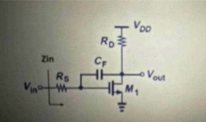
Find the low frequency input and output impedence exprrssions for the circuit below

Step by step
Solved in 3 steps with 3 images
