We examined the common source amplifier shown in the figure in the 5th experiment. The selection criterion of the input capacitance is Xcin = 0.1Rin: Calculate the required input capacitance value, Cin , if an input signal with a frequency of 2 kHz is applied. Şekitde gösterilen ortak source yükseltecini 5. deneyde incelemiştik Giriç kapasitesinin sEÇim Kriteri Xcin = 0.1Rin dir. 2 kHzlik giriç sinyali için gerekit kapasite, C değerini hesaplaymız. Circuit parameters / Devre Parametreleri R1 = 53 k2, R, = 17 k2 R1 RD Cout Vout D VDD M2 Cin G Vin R2 RS Cs O a. 74.19 nF O b. 86.55 nF O C. 49.46 nF O d. 61.82 nF O e. 43.28 nF
We examined the common source amplifier shown in the figure in the 5th experiment. The selection criterion of the input capacitance is Xcin = 0.1Rin: Calculate the required input capacitance value, Cin , if an input signal with a frequency of 2 kHz is applied. Şekitde gösterilen ortak source yükseltecini 5. deneyde incelemiştik Giriç kapasitesinin sEÇim Kriteri Xcin = 0.1Rin dir. 2 kHzlik giriç sinyali için gerekit kapasite, C değerini hesaplaymız. Circuit parameters / Devre Parametreleri R1 = 53 k2, R, = 17 k2 R1 RD Cout Vout D VDD M2 Cin G Vin R2 RS Cs O a. 74.19 nF O b. 86.55 nF O C. 49.46 nF O d. 61.82 nF O e. 43.28 nF

Power System Analysis and Design (MindTap Course List)
6th Edition
ISBN:9781305632134
Author:J. Duncan Glover, Thomas Overbye, Mulukutla S. Sarma
Publisher:J. Duncan Glover, Thomas Overbye, Mulukutla S. Sarma
Chapter12: Power System Controls
Section: Chapter Questions
Problem 12.16P

Related questions

Question
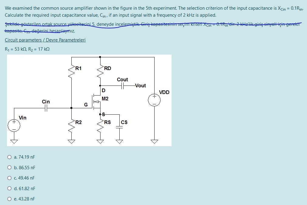
Transcribed Image Text:We examined the common source amplifier shown in the figure in the 5th experiment. The selection criterion of the input capacitance is Xcin = 0.1Rin:
Calculate the required input capacitance value, Cin , if an input signal with a frequency of 2 kHz is applied.
Şekitde gösterilen ortak source yükseltecini 5. deneyde incelemiştik Giriş kapasitesinin seçim kriteri Xcin - 0.1Rin dir. 2 kHzlik giriç sinyali için gerektt
tapasite, Cm değerini hesaplayınız.
Circuit parameters / Devre Parametreleri
R1 = 53 k2, R, = 17 k2
R1
RD
Cout
Vout
D
VDD
M2
Cin
G
Vin
R2
RS
cs
O a. 74.19 nF
O b. 86.55 nF
O c. 49.46 nF
O d. 61.82 nF
O e. 43.28 nF
Expert Solution
This question has been solved!
Explore an expertly crafted, step-by-step solution for a thorough understanding of key concepts.

Step by step
Solved in 2 steps with 2 images

Knowledge Booster


Learn more about
Need a deep-dive on the concept behind this application? Look no further. Learn more about this topic, electrical-engineering and related others by exploring similar questions and additional content below.Recommended textbooks for you
Power System Analysis and Design (MindTap Course …
Electrical Engineering
ISBN:
9781305632134
Author:
J. Duncan Glover, Thomas Overbye, Mulukutla S. Sarma
Publisher:
Cengage Learning
Power System Analysis and Design (MindTap Course …
Electrical Engineering
ISBN:
9781305632134
Author:
J. Duncan Glover, Thomas Overbye, Mulukutla S. Sarma
Publisher:
Cengage Learning