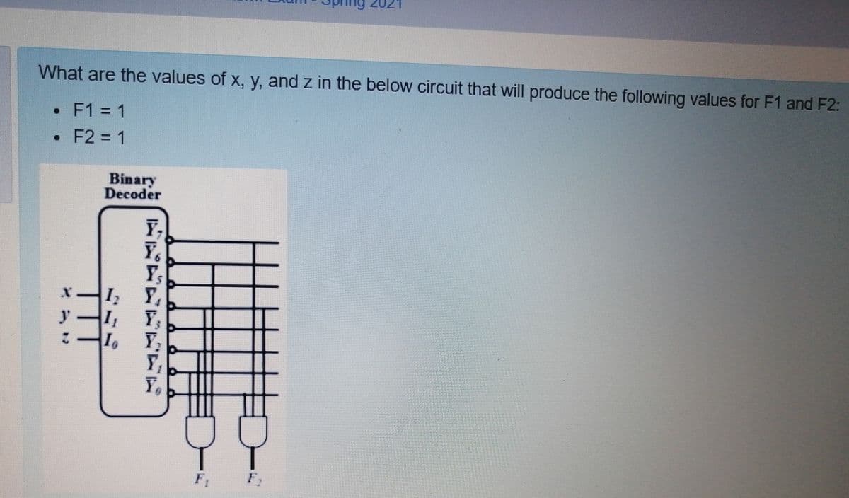
What are the values of x, y, and z in the below circuit that will produce the following values for F1 and F2: •F1 1 • F2 = 1 Binary Decoder Y, I Y I, Y I, Y y Y,


Q: What does the value on the wire X do? That is, what is the difference in the output of this circuit…
A: Answer for X = 0 When X = 0 , B bits will be selected. Therefore, S = A+B
Q: Create a table which shows the outputs of the circuit in signed decimal representation when the…
A:
Q: Time left 1:38:3 The circuit shown in figure performs addition as well as subtraction. If 4-bit…
A: As signal is S=1 , therefore it will perform subtraction Using 2'd complement method and result will…
Q: Perform the deconvolution operation between the following two signals:
A: clc;close all;t = 0:0.01:10;x = (t>=0 & t<1);h =…
Q: Using MSI (i.e. functional blocks), show how can you design a circuit that has two n-bit unsigned…
A: #include <stdio.h> #include <stdlib.h> #include <math.h> int main() { intn, A, B,…
Q: Compute the DTFT of the following signals: i) x[n] =[ ii) x[n] = [1, -2, 1]
A: Here is the detailed explanation of the solution
Q: 3- Design a 2-to-1 multiplexer by using UDP. The select signal is s, inputs are i0, il, and the…
A: The select signal is s, inputs are i0,i1, and the output is out. If the select signal s=x, the…
Q: Q11/Chose the correct answer for the output Q3 of the following circuit ( Assume that A= 1010101010,…
A: Here depending upon the value of output of D and T flip flop, the input to JK flip flop will be…
Q: discuss how we can use the PN generator in the transmitter (Tx) and receiver (Rx) circuits with a…
A: Use of the PN generator in the transmitter (Tx) and receiver (Rx) circuits with a simple example…
Q: x(n) y(n)
A:
Q: Simplify the following three K-Amps and draw the final simplified circuit. Use either Tina or…
A: Given, Kmap is : There are 3 octets which can be obtained from the above kmap. 1st octet = A '…
Q: Is the n the following circuit? EN DO 2X1 MUX DO 01 1-40-2 Decoder D1 B EN DO 2X1 MUX C 01 so B
A: Let's consider a scenario A=0 Then D0 is high. Thus the upper MUX will be selected. Now when B=0,…
Q: In _____, the level of the voltage determines the value of the bit. a. NRZ-I b. NRZ-L c. both (a)…
A: In NRZ-L (NRZ-Level), the level of the voltage determines the value of the bit. In NRZ-I…
Q: Plot the result of the convolution between the two signals shown below.
A: Step by step solution is given below-
Q: sA synchronous state machine has two inputs (X1 and X2) and two outputs (Z1 and Z2). The inputs…
A: Below is the answer to above question. I hope this will meet your requirement...
Q: For a block length of 100, Go Back N will reduce to 50% efficiency at the bit error rate of 10^ and…
A: For Go- Back -N sliding window protocol, the frame / packet error probability is given by:…
Q: Based on the given circuit, what are the values of J and K, when A=1, B=1, C=1? 4 to 1 MUX C' J…
A: Need to find the value of J and K, for the given circuit : When J gets input from 4:1 MUX and K…
Q: Chose the correct answer for the output F of the following circuit ( Assume that A= 101010, B=…
A: From the given circuit, F=((A⊕B)+(CD)')' Given A= 101010 B= 100101 C=111101 D =110100…
Q: TOllowing Tigure snowsS the fo circuit are A = 1 and B = 6. What is the outputs S3, S2, S1, and So?…
A: Initial value of Co = 1 A=1 = 0001 That is, A3=0, A2=0, A1=0, A0=1 B= 6 = 0110 So, B3=0, B2=1,…
Q: The circuit shown in figure performs addition as well as subtraction. If 4-bit binary numbers…
A: If s=1 it act as an subtractor
Q: We want to design a circuit that counts the number of 1s present on 3 binary inputs a, b, c and…
A: A) Truth table a b c y z 0 0 0 0 0 0 0 1 0 1 0 1 0 0 1 0 1 1 1 0 1 0 0 0 1 1 0 1 1 0…
Q: Please answer question C draw the circuit diagram. otherwise will downvote. Suppose there is a 4…
A:
Q: Shareholder A=2 shares, Shareholder B=3 shares, Shareholder C=3 shares, D=2 shares TOTAL=10 There is…
A: It is defined as Input means to provide the program with some data to be used in the program and…
Q: Course: Digital Electronics How to implement a full subtractor using a decoder IC 74138? and why…
A: IC 74138 is the 3*8 demux, which can be used in the full subtractor. Full subtractor has the three…
Q: b- What is the SNR for the following signal? time 0 1 3 60 8 10 signal 0.1 0.12 1.1 1.12 1.3 0.91…
A:
Q: In the Figure shown below, consider your binary sequence d(n): 1- Find the DPSK output signal (the…
A: We need to modulate and demodulate the given sequence using DPSK.
Q: y(n) x(n) + 1 sample delay 1.3 -1.2 1 sample delay -0.6 0.5 What difference equation corresponds to…
A:
Q: In a 6-bit two's complement system, A=010110, when perform X= - A, which of following statements is…
A: In a 6-bit two's complement system, A=010110, when perform X= - A, which of following statements is…
Q: What does this code do ? while(1) PTC->PDOR &= ~(0×OF << 3); delayMs(5); O writing '1' to PTC3,…
A: According to the information given:- We have to choose the correct option to satisfy the statement…
Q: wers are at the end of the chapter. Determine the sum (2) and the output carry (Cout) of a…
A: We have briefly described the half adder or the full adder , with the help of circuits truth tables…
Q: What does the value on the wire X do? That is, what is the difference in the output of this circuit…
A: Attached Handwritten solution image 01:
Q: Based on the given circuit, what are the values ?of J and K, when A=1, B=1, C=1 4 to 1 MUX C' J…
A: Following is the correct answer to your questions: j=1 k=1.
Q: 3-make deconvolution between two signals as shown deconv. x(t) h(t) dncete stepgl discte tep ugal as…
A: 3-make deconvolution between two...
Q: Given that A=0, B=0, C=1, what are the values of F an Y in the following circuit? Do D D2 3X8 D. Low…
A: For the below given circuit, need to find value of F and Y, when A = 0, B = 0 and C = 1. Where F…
Q: Given that A=0, B=0, C=1, what are the values of F an Y in the following circuit? (3 Points) A D D,…
A: Since A=0 B=0 and C=1 When we pass throw mux it will high f=1
Q: Q7/Chose the correct answer for the output Q of the following circuit (Assume that A=…
A:
Q: In a four -bit adder -subtractor and given that A(0101),B(0100),and M = 1 , what are the values of…
A: Correct answer is d. c1 = 0, v = 1
Q: A combinational circuit that has 4-inputs (a, b, c, d) and 4-outputs (w, x, y, z); the inputs (a, b,…
A: a b c d x y z x' y' z' 0 0 0 0 0 0 0 1 1 1 0 0 0 1 0 0 1 1 1 0 0 0 1 0 0 1 0 1 0 1 0 0 1 1 0…
Q: Create a table which shows the outputs of the circuit in signed decimal representation when the…
A: the carry out term will be set to one whenever two out of the three inputs in those case it doesnt…
Q: 10. If the values of inputs in a full adder are 0, 1, 1, what are the sum and carry values…
A: If the values of in a full adder are 0,1,1 then the sum and carry values
Q: (d) For an FM modulator with a modulation index of m = 1, and the given parameters as below. Va(t) =…
A:
Q: Q6/Chose the correct answer for the output Q3 of the following circuit ( Assume that A= 1010101010,…
A: Answer: The correct answer for the output Q3 of the following circuit where A = 1010101010 B=…
Q: Question 1: Consider the following 8-way multiplexer. Write F(a,b,c) as sum of minterms. 000 00 1 0…
A: Pin A B C f 0 0 0 0 0 1 0 0 1 1 2 0 1 0 0 3 0 1 1 0 4 1 0 0 1 5 1 0 1 1 6 1 1 0 0 7…
Q: Choose the most simple SOP expression from the K-map shown. AB 00 01 11 10 00 1 01 CD 11 10 Select…
A: EXPLANATION: The k-map minimizes the boolean expression on the basis of the groups that are formed…
Q: What is the size of my multiplier if I want a maximum output of 6-bits? create a diagram
A: A binary multiplier (multiplier) is a combinational logical circuit used to perform mutiplication on…
Q: 7. If the result of comparison at the highest bit of a 4-bit comparator has one input greater than…
A: The 4 bit comparator is used to compare the 2 4 bits number. The design is little bit complex but…
Q: Given that A=0, B=0, C=1, what are the values of F an Y in the following circuit? Do D D2 3X8 D Low…
A: A=0 and B=0 and c=1 Decoder do high D1 And everything is 0 and D1 is high When we pass this logic…
Q: The initial output of the following circuit is 1. If we apply 010101 at inputA (first bit is zero)…
A: Given data is The initial output of the circuit is 1 if we apply 010101 at input at A then…
Q: Using the De-multiplexing technique, what is the results of processing 0 and 0 and 0 ? O a. 0 O b. 3…
A: In de multiplexing signal from one source is converted into multiple output signal.which means de…
Q: Using MSI (i.e. functional blocks), show how can you design a circuit that has two n-bit unsigned…
A: The Code for the given question is in step-2.

Step by step
Solved in 2 steps with 1 images


- Can u create a multiplier circuit for just P3, P4 and P5Build a circuit that takes four bits as input: W, X, Y, Z. Treat WX as a 2-bit unsigned binary number, and treat YZ as a second 2-bit unsigned binary number. Your circuit should generate the output corresponding to the product of WX and YZ. You will need 4 bits of output for this problem.For example, if your input was 1011, your inputs correspond to 2 and 3. That product is 6, so your output will be 0110.Create a truth table for this problem, show all k-maps and minimizations, and build the corresponding (minimized) circuit. Use XOR, XNOR, NAND, and NOR as appropriate if it reduces the number of gates used.Implement a combinational circuit with three inputs x, y, and z and three outputs A, B, and C.When the binary input is equal to 0, 1, 2 or 3, then the output is equal to the input + 1.When the binary input is 4, 5, 6 or 7 then the binary output is equal to the input – 2.
- Based on the following image answer the following questions; a. Write a boolean algebra expression for each of Q0, Q1, Q2, and Q3: b. Draw a circuit that produces each of the functions from a single set of inputs A1 and A0: c. Each input combination of A1 and A0 represents a 2-bit binary number. How is this related to the outputs?We want to design a circuit that counts the number of 1s present on 3 binary inputs a, b, c and outputs that number in binary using 2 outputs y and z. For example an input of a=1, b=1, c=0 has two ones, so the output would be 210 = 102 i.e., y=1, z=0. a) Express y and z as sum of min‐terms of variables a, b and cb) Simplify the expressions for y and z using K maps.c) Draw the logical circuits for y and z using gates.Design a logical circuit that can sum two binary numbers formed by two bits each number. Use theminimum number of necessary bits for the output. Write the full procedure that you followed to getthe circuit. The complete procedure made by hand which should include the true table, Karnaugh diagramsand logical circuits.
- Design a circuit that takes three bits, X2, X1, X0 as input and produces one output, F. F is 1 if and only if 2<=X<=5 when X = (X2, X1, X0) is read as an unsigned integer. For example, if X2=1, X1=0, and X0=0, then the unsigned binary value is 100, which is 4, so the output would be 1. Your Assignment For This Problem Includes the Following Design the necessary circuit using Logisim to implement the situation described above. Use Kmaps for simplification. Be VERY careful to get the correct functions for your output before simplifying and designing the circuit with Logisim. You should minimize the circuit. Your circuit should have three inputs and one LED output. All inputs (X2, X1, X0) and output (F) should be labeled (in Logisim, not by hand). Please use these names to indicate the inputs and output so all projects are consistent. You should also include your name as a label on the circuit. Test your circuit to be sure it is working correctly.Consider two four bit numbers A and B, where either both the numbers are even or both of them are odd. Construct a combinational circuit which will perform the following operations: If A and B are both even, calculate A+B, else calculate A-BBuild a 4-bit adder with inputs a (input [3:0] a;) and inputs b (input [3:0]b;) with outputs c (output reg[3:0] c;). This circuit should be mapped to switches and LEDs so that you can see the answer. This circuit should not use the "+" operator and should be implemented with full-adders. Top module = module add_4bits(input [3:0]a, input[3:0]b, output reg[3:0]c);
- This question only reads: Build a decoder circuit. (Generic decoder?) What does this circuit do? If you added one more input, how many outputs would you need? How would a decoder be used?. Implement a circuit for the following problem using Logisim. The input to the circuit are 3 4-bit numbers, A,B,C. The sum of A and B is subtracted from C. The difference (result of subtraction) is compared with A. The circuit has 3 outputs lines depending on comparison. Use appropriate chips in Logisim for the operations mentioned Answer step by stepAn IC (number: ? ) is a parallel adder and is comprised of this number of full adders:_ . Connecting it properly with another IC (containing these gates: ? ) will increase its functionality. Set_? = 0 for subtraction.