what is the Moment at point A

Mechanics of Materials (MindTap Course List)
9th Edition
ISBN:9781337093347
Author:Barry J. Goodno, James M. Gere
Publisher:Barry J. Goodno, James M. Gere
Chapter3: Torsion
Section: Chapter Questions
Problem 3.12.4P: The stepped shaft shown in the figure is required to transmit 600 kW of power at 400 rpm. The shaft...

Related questions

Question
what is the Moment at point A
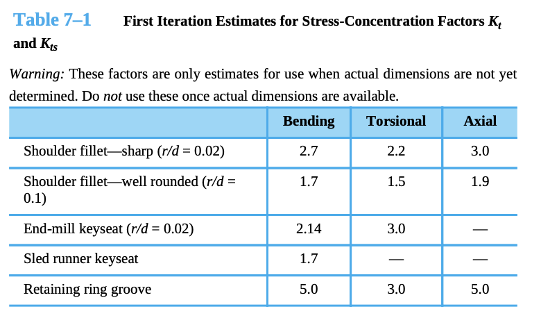
Transcribed Image Text:Table 7–1
First Iteration Estimates for Stress-Concentration Factors K,
and Kts
Warning: These factors are only estimates for use when actual dimensions are not yet
determined. Do not use these once actual dimensions are available.
Bending
Torsional
Axial
Shoulder fillet-sharp (r/d = 0.02)
2.7
2.2
3.0
Shoulder fillet-well rounded (r/d =
0.1)
1.7
1.5
1.9
End-mill keyseat (r/d = 0.02)
2.14
3.0
Sled runner keyseat
1.7
Retaining ring groove
5.0
3.0
5.0
![1. Consider the design of a shaft shown below. Use Table 7.1 and appendix A-20 to find the
properties and the associated SCFS. In this problem, use a D/d ratio of 1.5 and an r/d ratio of
0.02. The shaft is made from AISI 1015 CD steel. The Torque varies between 0 and 45N-m,
Veriable
between
while fixed loads are applied, as shown in the drawing.
327N
205M
k207e30-*20cm]
|
군
FA = - 3273 +900k cas
E= -259 - 562 EN]
%3D](/v2/_next/image?url=https%3A%2F%2Fcontent.bartleby.com%2Fqna-images%2Fquestion%2F3109647e-ec41-42bb-ae94-56d82d22e7e1%2F42b7b397-989d-4bd6-99f7-f64434bc7239%2Feusvwbe_processed.png&w=3840&q=75)
Transcribed Image Text:1. Consider the design of a shaft shown below. Use Table 7.1 and appendix A-20 to find the
properties and the associated SCFS. In this problem, use a D/d ratio of 1.5 and an r/d ratio of
0.02. The shaft is made from AISI 1015 CD steel. The Torque varies between 0 and 45N-m,
Veriable
between
while fixed loads are applied, as shown in the drawing.
327N
205M
k207e30-*20cm]
|
군
FA = - 3273 +900k cas
E= -259 - 562 EN]
%3D
Expert Solution
This question has been solved!
Explore an expertly crafted, step-by-step solution for a thorough understanding of key concepts.

Step by step
Solved in 3 steps with 3 images

Knowledge Booster


Learn more about
Need a deep-dive on the concept behind this application? Look no further. Learn more about this topic, mechanical-engineering and related others by exploring similar questions and additional content below.Recommended textbooks for you
Mechanics of Materials (MindTap Course List)
Mechanical Engineering
ISBN:
9781337093347
Author:
Barry J. Goodno, James M. Gere
Publisher:
Cengage Learning
Mechanics of Materials (MindTap Course List)
Mechanical Engineering
ISBN:
9781337093347
Author:
Barry J. Goodno, James M. Gere
Publisher:
Cengage Learning