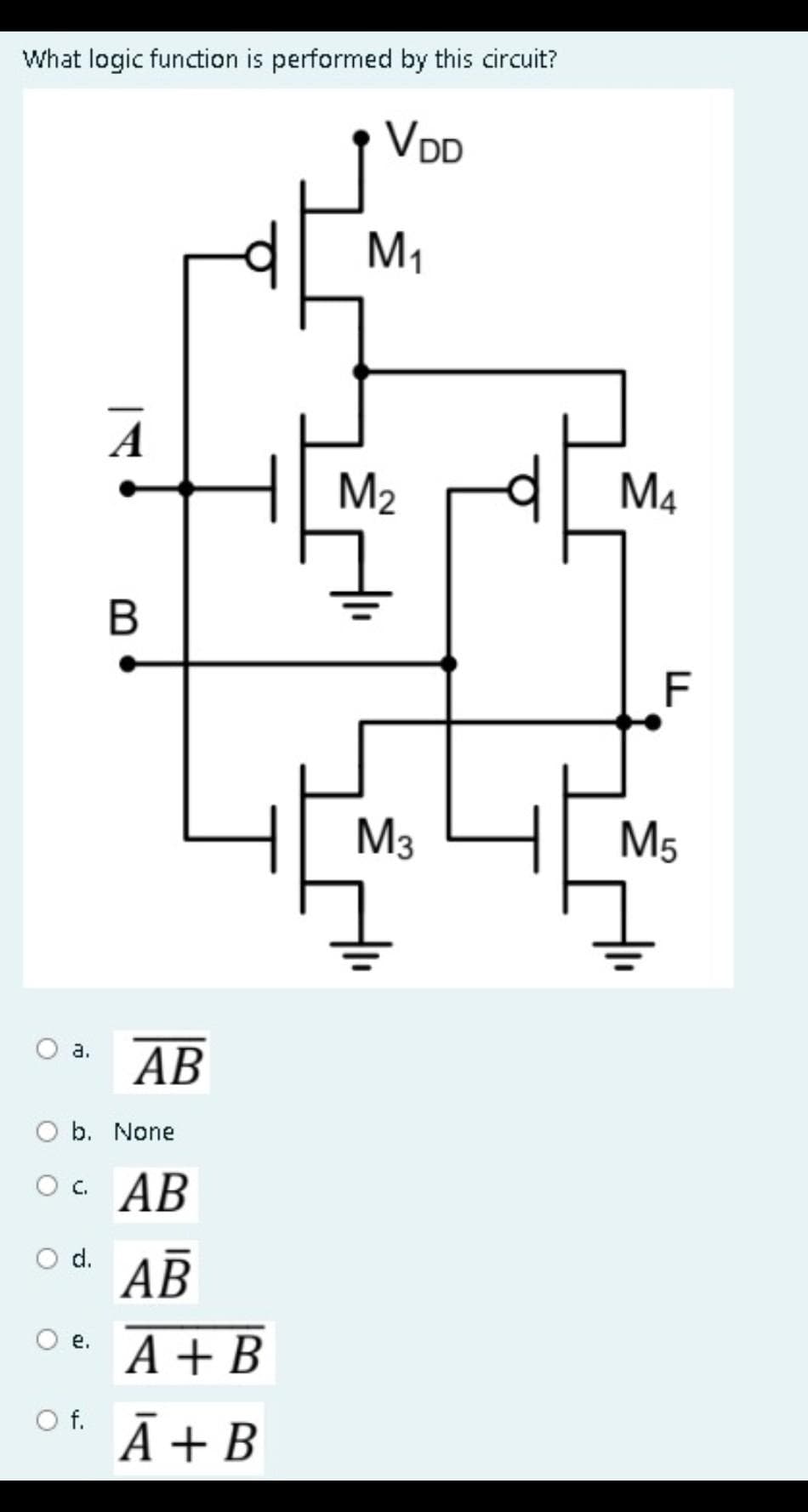
What logic function is performed by this circuit? VDD A B 나 M₁ M₂ M3 M4 F M5


Q: Design the following circuit so that the operating point is at the center of the load line, keep the…
A: Let us calculate the Thevenin equivalent across the base terminal. Now equivalent circuithereLet DC…
Q: 3.38 Obtain the impedance Z(s) of the network in Figure 3.35.
A: The total impedance of the circuit needs to be calculated and the same can be calculated by…
Q: 3. Reduce the block diagram shown in the figure to a single block, T(s) = C(s)/R(s). Show complete…
A: Given block diagram isWe need to reduce the given block diagram to single block and find transfer…
Q: Three houses in a small village are supplied from a 400 V 50 Hz three-phase pole-mounted transformer…
A: The question presents a scenario in a small village where three houses are supplied electricity from…
Q: iven the block diagram of the system below: x[n] Z-1 2 + 0.5 -2 1 Z Z Z -1 y[n]
A:
Q: 好 2 以 认 以 2K 試 认 张 Vo
A:
Q: "Calculate the equivalent impedance of the circuit shown when the frequency is 100 Hz. Solve the…
A:
Q: Consider the signal x(n) = [−1, 2, −3, 2, −1] ↑ with Fourier transform X(w). Compute the following…
A:
Q: Ques Mechanical energy is supplied to a d.c. at the 32.2 A at ROV. rode of 4200 Jls. The generator…
A: It is given that:Mechanical energy supplied = 4200 J/sCurrent (I) = 32.2 AVoltage (V) = 120 V
Q: Find (a)V₁ and (b)V₂ in the circuit in the figure using nodal analysis. + 8 mA 4 ΚΩ +
A: Circuit is given that
Q: 2- An electric heater takes 1.48 kW from a voltage source of 220 V. Find the resistance of the…
A: In an electric heater,Power usage, .Source voltage, .
Q: (b) Calculate the line voltage (in kV) at bus B and the complex power at the sending end of the…
A: given single-line diagram is load is at the sending…
Q: Q/3/A three phase controlled bridge rectifier is operated from a three phase Y- connected to a 250V,…
A: In this question we need to find the followingThe required firing angle if average output voltage is…
Q: The busbars of a gonerating station are divided into two soctions A and B by a busbar reactor rated…
A: Two bus bars A and B,connected through 8000KVA with 9% reactance.Two buses are connected to A and B…
Q: Determine the inverse z-transform of the following: 1-1/2-¹ (a) X(2) - |=| > 1/1/201 1-12 (b) X(z) =…
A:
Q: b. Solve for the source current/s. Ra ΕΓΚΩ + EΞ 20 V R₁ • 2 ΚΩ R₁ • 3 ΚΩ Ho R₂ Μ 3 3 ΚΩ R₂ R₂ ΣΚΩ 3…
A: The given circuit can be drawn like:
Q: Determine the voltage (Vo) 4 ΚΩ Μ a 10 ΚΩ
A: Circuit diagram is given as,
Q: Create the K-Map for the logic tables below: a. ABF 000 0 1 0 101 1 1 1
A:
Q: A DC voltage source has a source resistance variable from 5 0 to 25 Q and it is connected to a load…
A: A DC voltage source has,Source resistance, variableLoad resistance,
Q: = 7- Find the impulse response of ideal high pass filter with we 2TT 3
A: Since you have posted multiple questions, we will provide the solution only to the first question as…
Q: der the circuit show Figure 3. (a) the current in the 20.0 Q resistor and (b) the potential…
A: The given circuit diagram is shown below,
Q: Given the information appearing in Figure 2, determine Vce. 470 ΚΩ B =90 +22 V 9.1 ΚΩ Ic Figure 2…
A:
Q: Using two D flip-flops only, Design asynchronous Counter. The Counter counts in the sequence 1, 6,…
A: Requirement:An asynchronous Counter using D-Flipflops to count the sequence of,1637...Procedure:1.…
Q: A Single Area consists of 3 generating units (G1/G2/G3) with the following characteristics: G1: 200…
A: In this question we have to find the new generation output for G1.
Q: A 6-pole wave connected armature has 200 conductors and runs at 1000 rpm. The EMF generated is 500…
A: Poles, .Wave wound, .Armature conductors, .Speed, .EMF generated, .
Q: 4. In the circuit in figure, write the system of the mesh method and find i2. 10 2 40 V 10 WWW + Vo…
A:
Q: What is the mean value of half-wave rectified output signal if the peak voltage of input sine wave…
A: Peak value Given rectifier is a half wave rectifier.
Q: (a) Determine the heat energy required to convert 20 kg of water at 30°C completely to steam at…
A:
Q: 1- Derive the truth table for the following Logic Gates combination:
A: For the given logic circuit the truth table needs to be obtained and the same can be obtained by…
Q: Choose the correct answer (write the answer only). The open loop voltage gain for ideal op-amp is…
A: Choose the correct answer for the following question. Only need to choose correct answer.Mostly all…
Q: what is ON1 and SS1 is it a single component?
A: The above question is related to switching components in an impulse generator circuit.
Q: 7- Find X(z) for the sequence x(n)=()"³ cos((n-2))u(n-1) n-3
A: Since you have posted multiple questions we will provide the solution only to the first question a…
Q: Draw the Qoutput waveform if the inputs shown in the following figure are applied to a gated D…
A:
Q: 6 Compute the convolution y(n) = x(n) * h (n) of the following signals and check the correctness of…
A: Given:To determine:
Q: X> H W- N Determine the output M of the following logic circuits according to the inputs X, Y, Z and…
A: Logic circuit,Determine the output M.
Q: QUESTION 4 Q4.1 Show how can a series RLC can be used as a crude band-reject filter? Q4.2 How would…
A: Band reject filter:-If the overall position of the interference in the frequency plane has been…
Q: A 1bit modulator has the information signal! i(t) = 6sin2π * 10t + 3sin2π * 10t Calculate the…
A: The information signal i(t)= 6 sin 2 *10t+3 sin 2 *10t Step size () = 0.04 We need to find sampling…
Q: Question 1 Two positive 2nC point charges, denoted by q₁ and q2, are located at (0, 4cm, 0) and (0,…
A:
Q: J 되는
A: The differential voltage with respect to time needs to be calculated by using the charge of the…
Q: X CLK T A B B' A' J K D C C' -'1' y Current State Input Flip-flop Excitation Inputs A в с X T J K…
A: Given sequential circuit isWe need to create state transition table along with flip-flop inputs and…
Q: 3. A single-phase to single-phase cycloconverter "bridge type" with input voltage and frequency 150V…
A: Given cyclo converter in question is a step-down converter, which converts high-frequency AC voltage…
Q: A- A 10 kHz signal wanted to be sent and encrypted using FHSS with a factor of 10, if Af-5KHz…
A: FHSS stands for Frequency Hopping spread spectrum. It is a wireless communication technique where…
Q: 1. Calculate I. and V. using nodal analysis. окл Į 2mt ↑ 3km Io AMA 312KR 几
A:
Q: A 10-MVA 4.6-kV 60-Hz 6-pole three-phase synchronous generator has armature resistance of 2 ohms and…
A:
Q: Construct the asymptotic Bode plot of the magnitude response of the circuit below for V₂(s)/V₁(s). +…
A: Given circuit:To determine;Bode plot for magnitude response of
Q: Find the equivalent resistance in the follow circuit. 12V A B 4Ω 15Ω M 50 6Ω WwW
A:
Q: What will the breakdown strength of air be for small gaps (0.5cm) and large gaps (25cm) under…
A:
Q: Given the block diagram of the system below: x[n] Z Z 2 (a) Determine the system function H(z). (b)…
A: it is asked to find the system function H(z)
Q: Two alternating voltages are given by v1 = 15sinωt volts and v2 = 25 sin (ωt – π/6) volts. Plot both…
A: Given:To determineExpression of .
Q: 2₁ Z₁ 92 Z₂ Z₂ 3 93 U₁ = 10 V 93 =j5 A Z₁ = 10 +j10 Q Ξ, =j10 Ω 2 Ξ=-j5 Ω 2₁ = ? 2₂ = ? Výsledky…
A:

Step by step
Solved in 3 steps with 2 images


- You want to design an arithmetic comparison combined logic circuit. (a) List the steps that you will apply in the design approach. Design a 4-bit comparison (large-equal-small) circuit. Explain each step. With AND, OR, NOT gatesmake it happen. (b)By comparing the numbers 9 and 1 in the circuit you designed, the resultdiscuss.. Design a logic circuit that controls an elevator door in a three-story building. The circuithas four inputs. M is a logic signal that indicates when an elevator is moving (M=1) or stopped (M=0).F1, F2 and F3 are floor indicator signals that are normally LOW, and they go HIGH only when theelevator is positioned at the level of that particular floor. For example, when the elevator is lined uplevel with the second floor, F2=1 and F1=F3=0. The circuit output is the OPEN signal which isnormally LOW and is to go HIGH when the elevator door is to be opened.Direction: Analyze the given circuit and find the following: Logic Expression Simplified Logic Expression using Boolean Algebra Simplified Circuit
- question from DIGITAL LOGIC DESIGN book Sequential Logic :2. Perform Analysis Procedure on the following Circuit. Finally, do not forget to comment on the behaviorof the circuit. Perform all necessary analysis steps.and aslo perform each step.i) Minimize the logic expression Y = BC + AC + AB using Boolean Algebra rules (Pleaseshow the steps). ii) Draw the simplified logic circuit based on the minimum expression obtained from (i).Consider the Boolean expression: u = wx + yz + wx'z' + w'y. (a) Draw the Karnaugh map for u.(b) Use the map in part (a) to obtain the Karnaugh map for u'.(c) Express u' as a minimal sum of products.(d) Design a simple logic network for u'.
- A logic function f(A,B,C) implemented with 4x1 MUX circuit. Implement the same function with using only one 4x1 MUX. (B and C are selection inputs B=S1; C=S0)Given the following Logic function in standard SoP form F (A, B, C) = Σ (m4, m5, m7, m8, m10, m11, m13, m15) Simplify F through Karnaugh map using Minterms. (Show calculations) Simplify F through Karnaugh map using Maxterms. (Show calculations)I want to learn how to draw the circuit from the function in the digital logic design lab If she gives me a function how to draw it to a circuit with gates Easy explaining please
- Given the function G=(A’+B+C)(A’+B’+C’)(A+B+C) Draw the logic circuit diagram ofthe simplified OR-AND formDraw logic diagrams of the circuits that implement the original and simplified expressions in Problem 2.3 (a), (c), and (f).i) Analyze the logic circuit in Figure Q5(c) and obtain the Boolean expressionfor Z.ii) Construct a truth table from the logic circuit in Figure Q5(c) and explain it.