With the aid of a simple diagram, explain the j-notation method of phasor quantities. Four single-phase generators whose e.m.f.s can be represented by: e, = 20 sin @t; e, = 40 sin(@t + t/2); ez = 30 sin(@t – T/6); e̟ = nected in series so that their resultant e.m.f. is given by e = e, + ez + e; + e4. Express each e.m.f. and the resultant in the form a ± jb. Hence find the maximum value of e and its phase angle relative to ej. %3D 10 sin(@t – t/3); are con-
With the aid of a simple diagram, explain the j-notation method of phasor quantities. Four single-phase generators whose e.m.f.s can be represented by: e, = 20 sin @t; e, = 40 sin(@t + t/2); ez = 30 sin(@t – T/6); e̟ = nected in series so that their resultant e.m.f. is given by e = e, + ez + e; + e4. Express each e.m.f. and the resultant in the form a ± jb. Hence find the maximum value of e and its phase angle relative to ej. %3D 10 sin(@t – t/3); are con-

Introductory Circuit Analysis (13th Edition)
13th Edition
ISBN:9780133923605
Author:Robert L. Boylestad
Publisher:Robert L. Boylestad
Chapter1: Introduction
Section: Chapter Questions
Problem 1P: Visit your local library (at school or home) and describe the extent to which it provides literature...

Related questions

Question
Kindly show they got the answers I provided on the image.
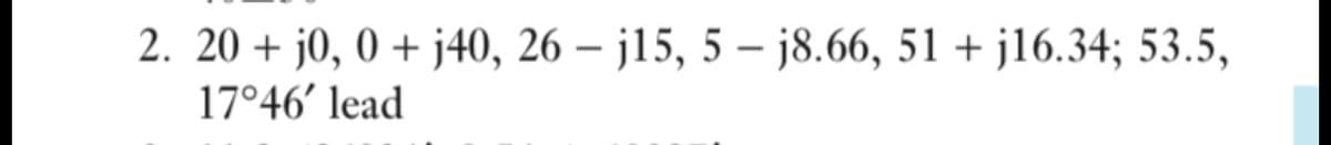
Transcribed Image Text:2. 20 + j0, 0 + j40, 26 – j15, 5 – j8.66, 51 + j16.34; 53.5,
17°46' lead
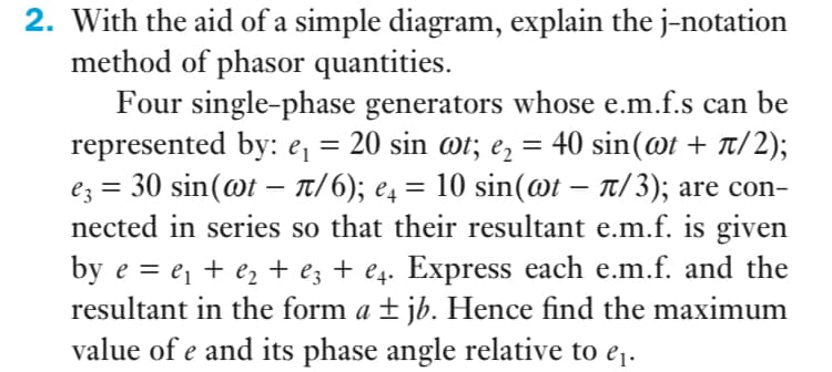
Transcribed Image Text:2. With the aid of a simple diagram, explain the j-notation
method of phasor quantities.
Four single-phase generators whose e.m.f.s can be
represented by: e, = 20 sin ot; e, = 40 sin(@t + t/2);
ez = 30 sin(@t – Tt/6); e4 = 10 sin(@t – t/3); are con-
nected in series so that their resultant e.m.f. is given
by e = e¡ + e, + e; + e4. Express each e.m.f. and the
resultant in the form a ± jb. Hence find the maximum
value of e and its phase angle relative to e¡.
Expert Solution
This question has been solved!
Explore an expertly crafted, step-by-step solution for a thorough understanding of key concepts.

Step by step
Solved in 3 steps with 3 images

Knowledge Booster


Learn more about
Need a deep-dive on the concept behind this application? Look no further. Learn more about this topic, electrical-engineering and related others by exploring similar questions and additional content below.Recommended textbooks for you
Introductory Circuit Analysis (13th Edition)
Electrical Engineering
ISBN:
9780133923605
Author:
Robert L. Boylestad
Publisher:
PEARSON

Delmar's Standard Textbook Of Electricity
Electrical Engineering
ISBN:
9781337900348
Author:
Stephen L. Herman
Publisher:
Cengage Learning

Programmable Logic Controllers
Electrical Engineering
ISBN:
9780073373843
Author:
Frank D. Petruzella
Publisher:
McGraw-Hill Education
Introductory Circuit Analysis (13th Edition)
Electrical Engineering
ISBN:
9780133923605
Author:
Robert L. Boylestad
Publisher:
PEARSON
Delmar's Standard Textbook Of Electricity
Electrical Engineering
ISBN:
9781337900348
Author:
Stephen L. Herman
Publisher:
Cengage Learning
Programmable Logic Controllers
Electrical Engineering
ISBN:
9780073373843
Author:
Frank D. Petruzella
Publisher:
McGraw-Hill Education

Fundamentals of Electric Circuits
Electrical Engineering
ISBN:
9780078028229
Author:
Charles K Alexander, Matthew Sadiku
Publisher:
McGraw-Hill Education

Electric Circuits. (11th Edition)
Electrical Engineering
ISBN:
9780134746968
Author:
James W. Nilsson, Susan Riedel
Publisher:
PEARSON

Engineering Electromagnetics
Electrical Engineering
ISBN:
9780078028151
Author:
Hayt, William H. (william Hart), Jr, BUCK, John A.
Publisher:
Mcgraw-hill Education,