20 0 jXN 500/0° V(rms) |Z. Source - Line - Load Figure P10.10 Full Alternative Text
Q: 2. A Y-connected balanced 3-phase source is supplying a balanced 3-phase load. The source phase A…
A: For Star connected system, Phase voltage = line voltage/sqrt(3). Line current = phase current. For…
Q: In the circuit shown in the figure, there is a load between the terminals a and b, consisting of the…
A:
Q: The load impedance in the power transmission system shown absorbs 6 kW and generates 8 KVAR (i.e.,…
A:
Q: 8. Two impedances, Z, = 0.8 + j5.6 Q and Zz = 8 - j16 Q, and a single-phase mot are connected in…
A: In this question we will find complex power for each impedance and total current and total power…
Q: Understand ac power concepts, their relationships to one another, and how to calculate them in a…
A: Given: I= (66.66-88.88j) mA I=111.11∠-53.13 mA
Q: A generating station supplies the following loads: 15000 kW, 12000 kW, 8500 kW, 6000 kW and 450 kW.…
A: Total loads are 15000 kW, 12000 kW, 8500 kW, 6000 kW and 450 kW.
Q: Q 2) A 110-V RMS, 60HZ source is applied to a load impedance Z. The apparent power entering the load…
A:
Q: Q2: For the circuit shown below, determine the apparent power delivered by the source, power…
A: First we will calculate node voltage by nodal analysis. power loss =I2×R. power factor= cos(angle…
Q: 9. The two loads in the circuit depicted below absorb the following power. Load, absorbs S = 6+j10…
A:
Q: The single phase load on an installation is 800 kW, 0.8 lagging power factor which works for 3000…
A:
Q: An industrial load is supplied through a transmission line that has a line impedance of 0.1 + j0.2…
A:
Q: The line-to-neutral voltage at the terminals of the balanced threephase load in the circuit shown is…
A:
Q: Q1. Two loads Z, 10 + j20 N , Z2 100 – j270, N are connected across a Vs=400Vrms, 50 Hz, source as…
A: Given, Vs=400 rms, 50 HzZ1=10+j20ΩZ2=100−j270Ω
Q: A balanced A connected source is connected to a balanced A connected load with an abc sequence set…
A: We are authorized to answer three subparts at a time, since you have not mentioned which part you…
Q: Under balanced operating conditions, consider the 3-phase complex power delivered by the 3-phase…
A: 1Real power P3ϕ is a cosine function of the total power and is given by,3 VLLILcosϕSo, it matches…
Q: 7 A load impedance, Z1 = 10 + j3 2, is connected to a source with line resistance equal to 1 N, as…
A: Hello. Since your question has multiple sub-parts, we will solve the first three sub-parts for you.…
Q: An impedance (inductive) ZL = (11.5 + j10) ohms is connected in parallel with an impedance…
A: The admittance of the inductive branch is given by, YL=1ZL=111.5+j10 =111.5-j10 11.5+j10 11.5-j10…
Q: The two loads shown can be described as follows: Load 1 absorbs an average power of 60 kW and…
A: a) Calculating root mean square value of load voltage is Calculating apparent power absorbed to…
Q: Two balanced loads are connected to a 240-kV rms 50-Hz line. Load 1 draws 30 kW at a power factor of…
A: Ans: a) Complex Power = 123.8 angle(43.86). Real power= 90 kw. Reactive Power = 85 kvar. b) Line…
Q: Consider the problem of maximizing the average power Z = R+jX absorbed by the load impedance Zjoad=…
A: (a) Given circuit is – Given values are –
Q: Given the three phase circuit illustrated below. Two balanced loads and the capacitors are connceted…
A: In the power system Calculate total complex power? Calculate line to line voltage Vs Find the power…
Q: The load impedance in the power transmission system shown absorbs 6 kW and generates 8 KVAR (i.e.,…
A:
Q: A three-phase delta connected source is connected to a three-phase delta connected load through…
A:
Q: The load impedance in the circuit shown is shunted by a capacitor having a capacitive reac- tance of…
A: In Network Phasor load current and voltage Real and imaginary power across load , transmission…
Q: To be transmitted is V, = 12 cos (59t + 10), the impedance of the generation system is neglected,…
A: Given: The supplied voltage to the transmission line V=12cos59t+10 The impedance of the generation…
Q: The instantaneous voltage across a circuit element is v(t) - 359.3 sin(wt + 15°) volts, and the…
A:
Q: Solve for the equivalent impedance and admittance seen at the source. Solve for is(t).
A:
Q: 7.17 A load impedance, Z, = 10+ j3 2, is connected to a source with line resistance equal to1 2, as…
A:
Q: For the circuit shown, what is the complex power, S, consumed by the 18 + 732 load impedance?…
A: To find complex power S by impedance 18 + j 32 ohm
Q: An investor own two large stores at Dubai. Both malls are connected in parallel and operating at an…
A: Given: An investor owns two large stores in Dubai. Both malls are connected in parallel and operate…
Q: A 50 Hz, 250 V single phase power line has the following loads placed across it in paralell; 4 kW at…
A:
Q: a) A source voltage of 230V rms at 50HZ is applied to a circuit having an impedance of (10+j12)…
A:
Q: The following 3-phase loads are connected to a 3- phase 400 V, 50 Hz power supply: [10] Load 1:…
A:
Q: 4. The maximum values of the alternating voltage and current are 400 V and 20 A respectively in a…
A: The solution is given below
Q: For the circuit shown, what is the complex power, S, consumed by the 18 + j32 load impedance?…
A: Given circuit: Load impedance, ZL=18+j32 Ω
Q: Solve part c.
A: Drawing the 1-phase equivalent circuit:
Q: (a) The voltage v across a load and the current i into the positive-polarity terminal are as follows…
A:
Q: For the circuit shown, given that Vab=208Z°, abc sequence, ZLine%3D0.1+j0.2 Q and ZLoad= 12+j4 Q.…
A: Magnitude of voltage VAB across load? 3 phase power system
Q: A 50 Hz, 250 V single phase power line has the following loads placed across it in parallel; 4 kW at…
A: Given Single phase 50 Hz,250 v power line Three parallel loadsLoad-1P1=4 kwPF1=0.8…
Q: A load Z draws 12 kVA at a power factor of 0.856 lagging from a 120-V rms sinusoidal source.…
A:
Q: LEARNING EXAMPLE f=60HZ,|Vine =34.5kV rms. Required:pf = 0.94leading %3D a Balanced load Balanced 24…
A: The solution is given below
Q: factor of the load, the power factor of the transmission line, and the power factor of the voltage…
A: The power factor is a ratio of the resistance to the impedance of the line. It is also the phasor…
Q: Q2: The two loads in the circuit shown below can be described as follows: Load 1: Absorbs an average…
A: According to question: The RMS value of load current 'I1' is calculated as The RMS value of load…
Q: Q2: For the circuit shown below, determine the apparent power delivered by the source, power…
A:
Q: A 3-phase Y-connected load draws power from a 3-phase Y-connected source. The source voltage,…
A: Since we only answer up to 3 sub-parts, we’ll answer the first 3. Please resubmit the question and…
Q: A11 kV,15 km length primary feeder connected to a balanced load of 950 kW at a power factor of 0.85…
A: We assumed three phase feeder as nothingI is mentioned about single phase or three phase. given…
Q: Q2: For the circuit shown below, determine the apparent power delivered by the source, power…
A:
Q: A 230 Vms, 50 Hz AC supplies a circuit consists of resistor 7 2 and inductor 31.8 mH connected in…
A:
Q: Solve
A: (a) The single phase equivalent circuit is drawn as:
Q: A generating station supplies the following loads : 15000 kW, 12000 kW, 8500 kW, 6000 kW and 45 kW.…
A: The solution can be achieved as follows.
The load impedance absorbs 2.5 kW and generates 5 kVAR. The sinusoidal voltage source develops 7.5 kW.
1. a) Find the values of inductive line reactance that will satisfy these
constraints.
2. b) For each value of line reactance found in (a), show that the
magnetizing vars developed equals the magnetizing vars absorbed.
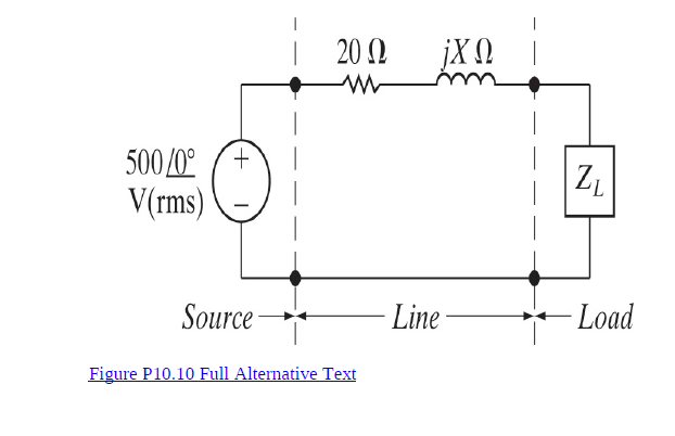
Trending now
This is a popular solution!
Step by step
Solved in 4 steps
- A load impedance, Zo = 10 + j 3 ohm, is connected to a source with line resistance equal to 3 ohm, as shown in the figure. Determine the average powers delivered to the load and absorbed by the line. The average powers delivered to the load and absorbed by the line are ________ and ____________ , respectively.S.2) The serial impedance of the 300 km power transmission line is 23 + j75 ohm / phase and the shunt acceptance is j500 microS / phase. A power of 50 MW with a power factor of 0.88 under 220 kV interphase voltage from the end of the power transmission line being shot. Using these data of the energy transmission line, a) Characteristic impedance of the energy transmission line, b) Natural apparent power of the energy transmission line according to the 220 kV interphase operating voltage, c) The values of the line parameters A, B, C and D of the transmission line using hyperbolic functions, d) Calculate the maximum power that the power transmission line can transmit.The network shown in Fig. P10.19 consists of a balanced 120 V (rms) Δ(delta)-source connected in a positive phase sequence, lossless transmission lines, and an unbalanced Δ(delta)-load with Zab = (6 + j4)Ω(ohm), Zbc = 4Ω(ohm), and Zca = 12Ω(ohm). Assign V12 a phase angle of 0°.
- five infinite-impedance volunteers,calibrated to read rms values,are connected as shown below. let R= 200, L=0.400H,C=6.0 Mf, and V=30.0 v. what's the reading of the voltmeter's V1,V2,V3,V4 and V5 if W= 200 rad/sFrom the circuit given below, How can I find the value of load Z for the maximum power transfer and the maximum average power transferred?The 9 Ω resistor in the circuit is replaced with a variable impedance Zo. Assume Zo is adjusted for maximum average power transfer to Zo. 1. a) What is the maximum average power that can be delivered toZo?2. b) What is the average power developed by the ideal voltage sourcewhen maximum average power is delivered to Zo?3. c) Choose single components from Appendix H to form animpedance that dissipates average power closest to the value in part(a). Assume the source frequency is 60 Hz.
- Under balanced operating conditions, consider the 3-phase complex power delivered by the 3-phase source to the 3-phase load. Match the following expressions, those on the left to those on the right. 0) Real power, Py (ii) Reactive power, Qu (ii) Total apparent power Sy (iv) Complex power, Sy (a) (V3 VLL. IL)VA (b) (V3 Vu sng) var (e) (V3 VLL. IL cos ø) W (d) Py +Qy Note that VLL is the rms line-to-line voltage, IL is the ms line current, and o is the power-factor angle.A circuit branch is found to have an equivalent impedance of Z=120−j45Ω. It is given that this impedance is a series combination of a 120Ω resistor and another passive component. If the circuit has a sinusoidal voltage source whose frequency is 120 Hz. What is the value of the component in series with the 120Ω resistor? (Note: Express the value assuming a metric scaling of μ(10-6). Provide your answer in decimal form, up to 3 decimal places.)The circuit with 3 parallel loads is described as follows. The load draws an average power of 1.8 kW (absorbing) and is behindlagging power factor 0.8. The load 2 draws 20 kVA and the leading power factor is 0.6. If the load is 3;3 Z j is an impedance of '2.5 5.0'. If the source frequency is 60 Hz, derive the steady-state equation for () V t s.
- A ower system is operating at 1000Mw, 132kV, 50Hz, with 0.8 p.f. laging in parallelwith another line at 750OMW, 132kV, 50Hz with 0.707 p.f. lagging. Both are interconnectedat the station and when the compensating device is on, the overall power factor isimproved to 0.9 lagging. Suggest suitable capacitors, shunt and series. Individual loadsand combined load are to improve power factor to 0.9 in all cases.1. Solve for the equivalent impedance and admittance seen at the source. Solve for is(t). 2. A load Z draws 12 kVA at a power factor of 0.856 lagging from a 120-Vrms sinusoidal source. Calculate: (a) the average and reactive powers delivered to the load, and (b) the peak current.The sending-end voltage in the circuit seen is adjusted so that the load voltage is always 13,800 V(rms). The variable capacitor is adjusted until the average power dissipated in the line resistance is minimum. 1. a) If the frequency of the sinusoidal source is 60 Hz, what is thevalue of the capacitance in microfarads?2. b) If the capacitor is removed from the circuit, what percentageincrease in the magnitude of Vs is necessary to maintain 13,800V(rms) at the load?3. c) If the capacitor is removed from the circuit, what is thepercentage increase in line loss?