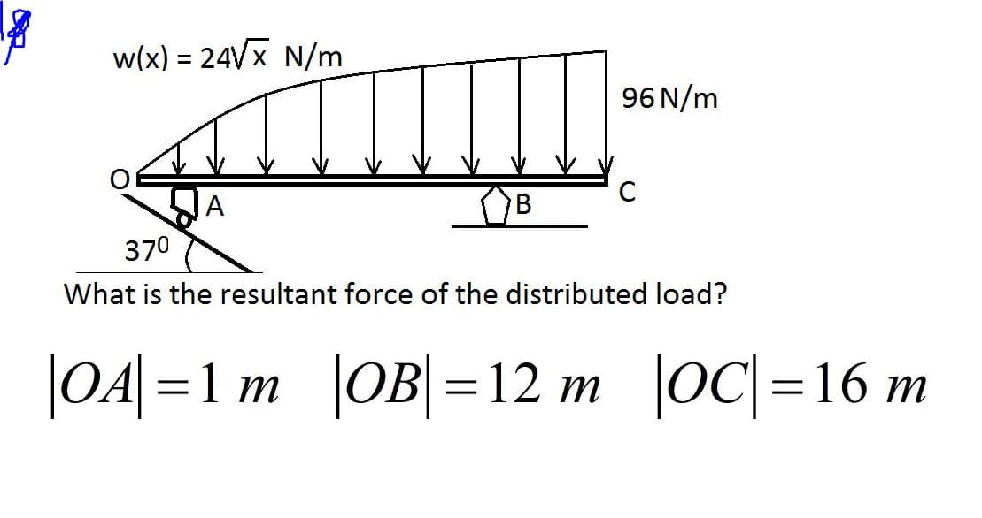
w(x) = 24VX N/m %3D 96 N/m A B 370 What is the resultant force of the distributed load?


Q: Mechanics of Deformable Bodies The rigid beam of negligible weight is supported by a pin at o and…
A:
Q: Q5/ The axial force applied on the beam is :equal to 10 kN he100 mm 2m 4m b-50 mm Non of these 10 KN…
A: Find the axial force on th beam.
Q: If you know traction (stress vector) acting on N planes through a point, you can find traction…
A: Solution: For the proper explanation, we need to understand Cauchy's law. According to this law, a…
Q: 30° Q 15° A 48° 40° 120 mm 200 mm
A: The moment of a force can be determine by calculating the cross-product of position and force…
Q: The steel I-beam in the drawing has a weight of 1.20 x 10° N and is being lifted at a constant…
A: Draw the free body diagram for the above problem as follows.
Q: • Dimensions: width, b = 54 mm, depth, d = 110 mm, and height, h = 284 mm. • The modulus of…
A: Given:b=54 mmd=110 mmh=284 mmE=3 GPav=0.45θ=70°∆d=0.40 mm
Q: A free body diagram of a section of a beam is shown. The reaction force (RA) is 38 kN. What is the…
A:
Q: The state of 2D stress at a point is given by a matrix [100 30] MPa MPа 30 20 Ox Txy Tyx Oyy The…
A:
Q: Q3: A wire 10m long of cross section area 1.22 cm? elongates by 1.5 cm when 4.5 kg is suspended from…
A: Given data length of wire (L) = 10 m cross sectional area (A) = 1.22 cm2 = 122 mm2 Deflection (δ)…
Q: An alumin um rod with the rod axis oriented in the z-direction is subjected to T20 = 10MPa, which is…
A:
Q: Figure 1: y P = 400 kN 30° 1000 mm A Area 30 mm 20 mm In Figure 1, the equilibrium shear force…
A: Given data :- force = 400KN find the shear force at point A.
Q: Question 6 – SFD & BMD - Simply Beam (Point) From the beam shown below, i) Draw the Free Body…
A: Consider upward force & CW moment as (+)ve and downward force & CCW moment as (-)ve. Net…
Q: 800 N 600 N 1200 N · m A В 1 m- -1 m 1 m- -1 m- VW) V1 3 -xon) V2 V3 What is the shear force value…
A: The answer to the above question is V1 = 450 N. option (c) The sign convention for the shear force…
Q: Determine the slope at point B of the beam shown in Figure. EI is constant.
A: Draw the free body diagram of the beam and calculate reaction force and reaction moment at point C.…
Q: 15. The shear force at point C in [KN]: a) 12 b) 15 c) 16.5 d) 13.5 e) None +₁.5m +15m +1 B m 11.5m…
A:
Q: 30 kN 50 kN C B 1 m 3 m 2 m
A: Let us consider that the reaction at B is RB and reaction at D be RD . Calculating the reaction at…
Q: | 5 kips 30 kip • ft I = 90 in.". 6 in. A B D NA 2 in. 4 ft 4 ft FIG. P5.36
A: The maximum normal bending stress in the beam can be calculated using the formula given below as-…
Q: 15. A 1 cmx 20 cm sheet of water is deflected as shown in Figure. The magnitude of the horizontal…
A:
Q: 1200 N/m В 1.5 m- -1.5 m- 450 N 600 N/m Mc Nc V 0.5 m
A:
Q: 8KN 2KN am 3m
A: given; w=2kN/m
Q: 20 ksi 40 ksi 60 ksi The differential element above represents the state of plane stress at a point…
A: As per given question Which of the following best represents the orientation of the maximum in-plane…
Q: Determine the torsional shear stress in the shaft section AB and BC. There is a fixed support at C…
A:
Q: Two beams A and B are simply supported, subjected to identical loads. The two beams have same width,…
A: Section modulus: It is the ratio of second moment of area and distance from Neutral axis to the…
Q: The shear force of section K in the structure is F
A: GIVEN:
Q: Passing an exploratory section through the body and exposing the internal forces acting on the…
A: Exploratory section or oblique plan - An oblique plan exposes the internal surfaces of a body…
Q: w(x) = 24VX N/m 96 N/m C B 370 What is the distance between the application point of the resultanf…
A: Given: The equation of load profile, w(x) = 24√x The length of beam, L = OC = 16 m
Q: Question 2 A 100 mm long solid cylindrical part shown here has 15 mm diameter. The loads on the part…
A: Given, Diameter of shaft, d=15mmLength of the cylindrical shaft, L=100mmAxial…
Q: Sketch the internal shear force diagram using either the graphical method or the sectioning method…
A:
Q: Q3/ Replace the loading system acts on beam shown in Fig. (3) by an equivalent system consists…
A:
Q: Question 1 continued 4 of 5 b) Fig. 2 shows the shear force (KN) and bending moment (KNm) diagrams…
A: The shear force diagram of the loading on the beam is shown below.
Q: A IC B 3 ft 12 ft
A: Given, loading (w)=100lb/ft To convert uniformly varying load, Area of the loading curve gives the…
Q: 3. Calculate the internal resultant loadings at point C. 150 N/m 50 N/m 20 Nm A |C 1.5 m 1.5 m
A: Given ,
Q: 2. The structure is connected by a pin joint at point A and by a cable of length L at points B and…
A: The free-body diagram of the above structure is given as, Apply force equilibrium in the vertical…
Q: Determine the friction force at the surface of contact.
A: Part (a) The 500 N can be resolved as,
Q: 10 N 20 N 10 N E M C B 10 N 6.0m 4.0m D F A H J L 0 8 BAYS @ 3.0 m EACH 20 N • The force at member…
A:
Q: Problem Number 2: A horizontal boom 11.5 M in length, AE is supported by guy wires from A to B,C and…
A:
Q: tind the stresses in the steel and aluminum rods when the temperature rises to 60 C° and the…
A: Given: The temperature rise, dT = 60 C The intensity of load = 10 kN/m
Q: Given points M(-1, 2, 1), N(3, -3, 0), and P(-2, -3, -4), find: (a) RMN : (b) RMN + RMP; (c) ]rM|;…
A: Given points M-1,2,1, N3,-3,0, P-2,-3,-4 (a)…
Q: 7 ft 80kN 60° 588 B looks 50 g 80° You 36 38 Cs 66 4f+ 3 ft P₁) Find force for all member? 200KN 2ft…
A: To find: The forces for all the member. FBD: The free body diagram shown below:
Q: =, Try to use the first processing method to solve the equivalent load vector of the illustrated…
A:
Q: 1. Find the external reactions, the axial force ,shear force and bending moment at the crown C. 30…
A: To find external support reactions and internal forces at point C
Q: Q3: A wire 10m long of cross section area 1.22 cm? elongates by 1.5 cm when 4.5 kg is sUspended from…
A:
Q: n Question 1.2 A material has a modulus of elasticity E and a shear modulus of 0.4x E. The Poisson's…
A: Given data: Elasticity=EG=0.4E Need to determine the poison's ratio of the material.
Q: 1- +4 P = 3.1193x10 P=1.9399X10 a= 295.07 m 2 at eltituce 12 Km Find P,P, T at G Icm ?
A:
Q: 6. Assuming that the wind force reverses in direction, the maximum service load based on a combined…
A:
Q: Example-6 X 2 X 1 B4 В з k M2 M1 f (t) В 2 B1
A: Given data: - The stiffness of the spring is k. The damping coefficients are B3 and B4. The…
Q: Find the shear stress on the cross-section shown if a force of 2000 N acts as shown 2000 N 2.5 cm 3…
A:
Q: The beam ABis attached to the wall in the rz plane by a fixed support at A. A force of F = (- 156i +…
A:
Q: Example 14: An elastic rubber band is attached to points A and B as shown in Fig. Determine its…
A:
Q: (2) The strength condition of composition of bending and torsion is _M₂_ √ M² + (aT)² ≤ [0_16] J.= W…
A:


Step by step
Solved in 2 steps with 2 images


- Repeat Problem 11.2-3 assuming that R= 10 kN · m/rad and L = 2 m.A part is loaded with a combination of bending, axial, and torsion such that the following stresses are created at a particular location:Bending: Completely reversed, with a maximum stress of 60 MPaAxial: Constant stress of 20 MPaTorsion: Repeated load, varying from 0 MPa to 70 MPaAssume the varying stresses are in phase with each other. The part contains a notch such that Kf,bending = 1.4, Kf,axial = 1.1, and Kf,torsion = 2.0. The material properties are Sy = 300 MPa and Su = 400 MPa. The completely adjusted endurance limit is found to be Se = 160 MPa. Find the factor of safety for fatigue based on infinite life, using the Goodman criteria. If the life is not infinite, estimate the number of cycles, using the Walker criterion to find the equivalent completely reversed stress. Be sure to check for yielding.An automobile engine develops a maximum torque of 162Nm. The low gear ratio of transmission is 2.75, while the back axle ratio is 4.25. The effective wheels radius is 0.325m and the co-efficient of friction between the tyre and the road surface is 0.6. If the permissible shear stress is 32373 X 104Pa. Determine the maximum shaft diameter. Assuming that the load is nearly torsional. What is maximum load permissible on each wheel?
- Total Load = 40 + 150 + 100 + 60 + 40 = 390KNRD = 217.62 RB = 172.38 Don't skip solutions thanks!A 4-T crane is used to lift a 3m x 1.2m x 200mm pre-cst panel. A preader beam is needed to ensure the proper distribution of load in the lifting chains. Consider modulus of elasticity, E=200,000 MPa, allowable shearing stress of lifting pin is 50 MPa, the steel plate used in the spreader beam has an allowable bearing stress of 40 MPa. (All measurement in the figure is in millimeters) 1. Determine the total load in kN, the crane has to carry the the lifting accessories (spreader beam, lifting chains and hooks) has a total mass of 720 kgs. if 2. Determine the average normal stress on each leg of the lifting chain A and B. 3. Determine the required diameter (d) in millimeters of the lifting pin if the allowable shearing stress must not be exceeded (Round to the nearest whole number). 4. Determine the required thickness (t) in millimeters of the steel plate to be used if the allowable bearing stress must not be exceeded. (Round to the neareat whole number)This is part of alarger super position problem and I was able to solve for a moment and a concentrated load but this distributed load is confusing me. E = 200 GPa I = 216*10^6 mm^4 w = 81 kN/m d = 1.5 m I ended up getting an answer near -12 mm of diflection but that is an incorrect according to the grader. What would the equation for the elastic curve of this problem be? What is its value at point B? thank you so much!
- Solve the problem below. For your final answer, use whole number. An extra flexible 8 × 19 steel wire rope of 38 mm diameter is used with a 2 m diameter hoist drum to lift 70 kN of load. The wire rope has a length of 900 meters. The maximum speed is 3 m / s and the acceleration is 1.5 m / s2. The diameter of the wire may be taken as 0.05 d, where d is the diameter of wire rope. The modulus of elasticity of the entire rope is 84 × 103 N/mm2. The weight of the rope is 53 N/m length. Determine the effective load during acceleration of load in kN.A link of a valve gear has to be curved in one plane, for the sake of clearance. Estimate the maximum tensile and compressive stress in the link if the thrust is 2500 N. (Cam bridge) ANSWER: maximum tensile 38.0 MN/m2; maximum compressive 46.0 MNIm2. Please show the solution to get the answer.Mechanical design The maximum load in a rotating shaft is subjected to bending moment of 1 kN.m and a torque of 1 kN.m. The member is made of steel the Ultimate Tensile Strength 440 MPa, Yield Tensile Strength 370 MPa. With a safety factor of 4, kt = km = 1.5 and keyway stress consternation is presented. According to the maximum shear stress theory, the shaft diameter will be: a. 160 mm b. 74 mm C. 145 mm d. 92.5 mm e. 60 mm f. 66 mm
- complete solution and drawing. if u can please add some explanation thankyou FN = 49 MN = 101 SN = 94 Figure below is a shaft which is held by different type of bearings. Calculate the resultant internal loadings at E3) A flange coupling is to connect two 60mm shafts. The hubs of the coupling are 120mm, 100mm thick, & the flange webs are 20 mm thick. Six M16 bolts fasten the flange from a 165 bolt circle. The keyway is 15mm shorter than the hub’s thickness & the key is 15mm x 15mm. The coupling transmits 45kW @ 450rpm. The yield point in shear for all materials is half of its yield point in tension or compression. Yield tensile strength is 0.75 of ultimate strength of the materials. The Sult is 448N/mm2 . Find: (a) the shear stress in key; (b) the bearing stress in key; (c) the shear stress in bolts; (d) bearing stress in flange.The material of a certain transmission shaft uses AISI 1030 HR, its yield strength is 260 MPa, the transmission torque of this shaft is 160 N·m, and it is subjected to a uniform axial tension of 0.5 kN. Please calculate according to the Distortion energy theory. The minimum shaft diameter with a safety factor n of 2.5 (to 2 decimal places).