1. Find the external reactions, the axial force ,shear force and bending moment at the crown C. 30 10t H 5V3 1 2 10m 10m
1. Find the external reactions, the axial force ,shear force and bending moment at the crown C. 30 10t H 5V3 1 2 10m 10m

Mechanics of Materials (MindTap Course List)
9th Edition
ISBN:9781337093347
Author:Barry J. Goodno, James M. Gere
Publisher:Barry J. Goodno, James M. Gere
Chapter6: Stresses In Beams (advanced Topics)
Section: Chapter Questions
Problem 6.8.4P: Solve the preceding problem for a W 200 × 41,7 shape with h = 166 mm, h = 205 mm. rw = 7.24 mm, tE=...

Related questions

Question
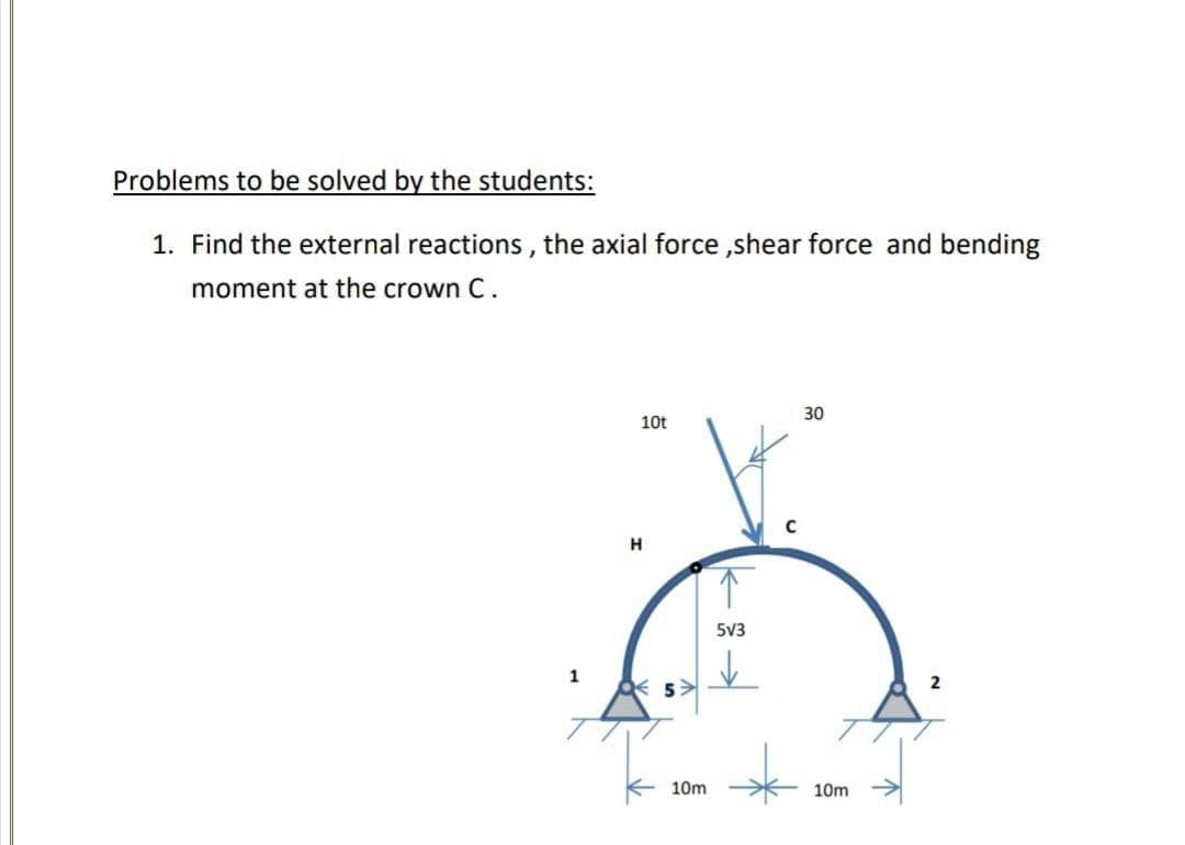
Transcribed Image Text:Problems to be solved by the students:
1. Find the external reactions , the axial force ,shear force and bending
moment at the crown C.
30
10t
5V3
1
长5>
2
10m
10m
Expert Solution
This question has been solved!
Explore an expertly crafted, step-by-step solution for a thorough understanding of key concepts.

Step by step
Solved in 2 steps with 1 images

Knowledge Booster


Learn more about
Need a deep-dive on the concept behind this application? Look no further. Learn more about this topic, mechanical-engineering and related others by exploring similar questions and additional content below.Recommended textbooks for you
Mechanics of Materials (MindTap Course List)
Mechanical Engineering
ISBN:
9781337093347
Author:
Barry J. Goodno, James M. Gere
Publisher:
Cengage Learning
Mechanics of Materials (MindTap Course List)
Mechanical Engineering
ISBN:
9781337093347
Author:
Barry J. Goodno, James M. Gere
Publisher:
Cengage Learning