y 960 mm? AT = -25°C 80 GPa 165 kN 15.7 x10⁻⁶/°C (1) 1920 mm? (2) A %3D B E2 160 GPa %3D 19.7 x10⁶/°C %3D 2000 mm 2600 mm A composite axial structure consists of two rods joined at flange B. Rods (1) and (2) are attached to rigid supports at A and C, respectively. A concentrated load P is applied to flange B in the F1 kN F2 kN direction shown. MPа Determine the internal forces and normal stresses 01 in each rod after the temperature changes by the indicated AT. (+= tension, 02 MPa - = compression) Also, determine the deflection of flange B in the x direction. (+ = right, – = left) UB mm 1st 2nd 3rd Enter attempt Rod properties I| ||||
y 960 mm? AT = -25°C 80 GPa 165 kN 15.7 x10⁻⁶/°C (1) 1920 mm? (2) A %3D B E2 160 GPa %3D 19.7 x10⁶/°C %3D 2000 mm 2600 mm A composite axial structure consists of two rods joined at flange B. Rods (1) and (2) are attached to rigid supports at A and C, respectively. A concentrated load P is applied to flange B in the F1 kN F2 kN direction shown. MPа Determine the internal forces and normal stresses 01 in each rod after the temperature changes by the indicated AT. (+= tension, 02 MPa - = compression) Also, determine the deflection of flange B in the x direction. (+ = right, – = left) UB mm 1st 2nd 3rd Enter attempt Rod properties I| ||||

Mechanics of Materials (MindTap Course List)
9th Edition
ISBN:9781337093347
Author:Barry J. Goodno, James M. Gere
Publisher:Barry J. Goodno, James M. Gere
Chapter5: Stresses In Beams (basic Topics)
Section: Chapter Questions
Problem 5.9.5P: A sign for an automobile service station is supported by two aluminum poles of hollow circular cross...

Related questions

Question
Transcribed Image Text:A,
960 mm?
ΔΤ
-25°C
E1
80 GPa
165 kN
a1 =
15.7 x10-/°C
(1)
(2)
А, —
1920 mm?
E, =
160 GPa
19.7 x10/°C
2000 mm
2600 mm
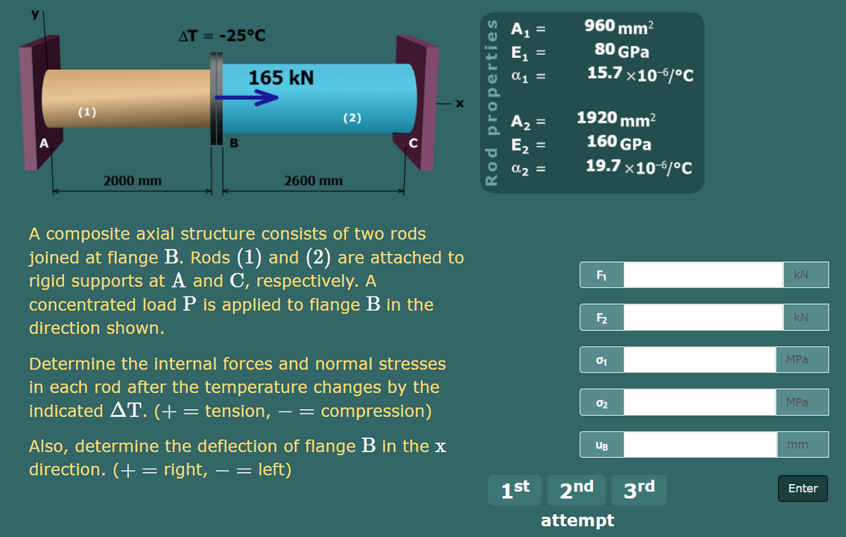
A composite axial structure consists of two rods
joined at flange B. Rods (1) and (2) are attached to
rigid supports at A and C, respectively. A
concentrated load P is applied to flange B in the
F1
kN
F2
kN
direction shown.
Determine the internal forces and normal stresses
01
MPа
in each rod after the temperature changes by the
indicated AT. (+= tension, – = compression)
02
MPa
Also, determine the deflection of flange B in the x
direction. (+ = right,
UB
mm
= left)
1st
2nd
3rd
Enter
attempt
Rod properties
I| ||||
Expert Solution
This question has been solved!
Explore an expertly crafted, step-by-step solution for a thorough understanding of key concepts.

This is a popular solution!

Trending now
This is a popular solution!

Step by step
Solved in 3 steps with 2 images

Knowledge Booster


Learn more about
Need a deep-dive on the concept behind this application? Look no further. Learn more about this topic, mechanical-engineering and related others by exploring similar questions and additional content below.Recommended textbooks for you
Mechanics of Materials (MindTap Course List)
Mechanical Engineering
ISBN:
9781337093347
Author:
Barry J. Goodno, James M. Gere
Publisher:
Cengage Learning
Mechanics of Materials (MindTap Course List)
Mechanical Engineering
ISBN:
9781337093347
Author:
Barry J. Goodno, James M. Gere
Publisher:
Cengage Learning