You are a biomedical engineer working for a small orthopaedic firm that fabricates rectangular shaped fracture fixation plates from titanium alloy (model = "Ti Fix-It") materials. A recent clinical report documents some problems with the plates implanted into fractured limbs. Specifically, some plates have become permanently bent while patients are in rehab and doing partial weight bearing activities. Your boss asks you to review the technical report that was generated by the previous test engineer (whose job you now have!) and used to verify the design. The brief report states the following... "Ti Fix-It plates were manufactured from Ti-6AI-4V (grade 5) and machined into solid 150 mm long beams with a 4 mm thick and 15 mm wide cross section. Each Ti Fix-It plate was loaded in equilibrium in a 4-point bending test (set-up configuration is provided in drawing below), with an applied load of 1000N. The maximum stress in this set-up was less than the yield stress for the Ti-6Al-4V material. Based on my engineering analysis and assuming similar loading conditions in vivo, I conclude that this design can withstand such loading conditions without bending." The report is signed by the former test engineer. You recall a picture from the Orthopaedic Engineering class you took at Clemson. It showed that fracture repairs can expose plates to loading conditions that are similar to a 3-point bend test. You begin to explore whether the test conditions used by the former test engineer fully captured possible physiological loading conditions in patients with the bent plates. Material Ti-6Al-4V grade 5 Process Annealed Elastic Modulus (GPa) 115 Yield Strength (MPa) 880 Ultimate Tensile Strength (MPa) 950 Ultimate Shear Strength (MPa) 550 III Netol Q2 Calculate the shear force and bending moments for 4 point test conditions used by the test engineer. Report the maximum stress due to bending and draw appropriate shear and bending moment diagrams, as discussed in class lecture. Reference points A-D in your diagrams.
You are a biomedical engineer working for a small orthopaedic firm that fabricates rectangular shaped fracture fixation plates from titanium alloy (model = "Ti Fix-It") materials. A recent clinical report documents some problems with the plates implanted into fractured limbs. Specifically, some plates have become permanently bent while patients are in rehab and doing partial weight bearing activities. Your boss asks you to review the technical report that was generated by the previous test engineer (whose job you now have!) and used to verify the design. The brief report states the following... "Ti Fix-It plates were manufactured from Ti-6AI-4V (grade 5) and machined into solid 150 mm long beams with a 4 mm thick and 15 mm wide cross section. Each Ti Fix-It plate was loaded in equilibrium in a 4-point bending test (set-up configuration is provided in drawing below), with an applied load of 1000N. The maximum stress in this set-up was less than the yield stress for the Ti-6Al-4V material. Based on my engineering analysis and assuming similar loading conditions in vivo, I conclude that this design can withstand such loading conditions without bending." The report is signed by the former test engineer. You recall a picture from the Orthopaedic Engineering class you took at Clemson. It showed that fracture repairs can expose plates to loading conditions that are similar to a 3-point bend test. You begin to explore whether the test conditions used by the former test engineer fully captured possible physiological loading conditions in patients with the bent plates. Material Ti-6Al-4V grade 5 Process Annealed Elastic Modulus (GPa) 115 Yield Strength (MPa) 880 Ultimate Tensile Strength (MPa) 950 Ultimate Shear Strength (MPa) 550 III Netol Q2 Calculate the shear force and bending moments for 4 point test conditions used by the test engineer. Report the maximum stress due to bending and draw appropriate shear and bending moment diagrams, as discussed in class lecture. Reference points A-D in your diagrams.

Elements Of Electromagnetics
7th Edition
ISBN:9780190698614
Author:Sadiku, Matthew N. O.
Publisher:Sadiku, Matthew N. O.
ChapterMA: Math Assessment
Section: Chapter Questions
Problem 1.1MA

Related questions

Question
Transcribed Image Text:You are a biomedical engineer working for a small orthopaedic firm that fabricates rectangular shaped fracture
fixation plates from titanium alloy (model = "Ti Fix-It") materials. A recent clinical report documents some problems with the plates
implanted into fractured limbs. Specifically, some plates have become permanently bent while patients are in rehab and doing partial
weight bearing activities.
Your boss asks you to review the technical report that was generated by the previous test engineer (whose job you now have!) and used to
verify the design. The brief report states the following... "Ti Fix-It plates were manufactured from Ti-6Al-4V (grade 5) and machined into
solid 150 mm long beams with a 4 mm thick and 15 mm wide cross section. Each Ti Fix-It plate was loaded in equilibrium in a 4-point bending
test (set-up configuration is provided in drawing below), with an applied load of 1000N. The maximum stress in this set-up was less than the
yield stress for the Ti-6Al-4V material. Based on my engineering analysis and assuming similar loading conditions in vivo, I conclude that this
design can withstand such loading conditions without bending." The report is signed by the former test engineer.
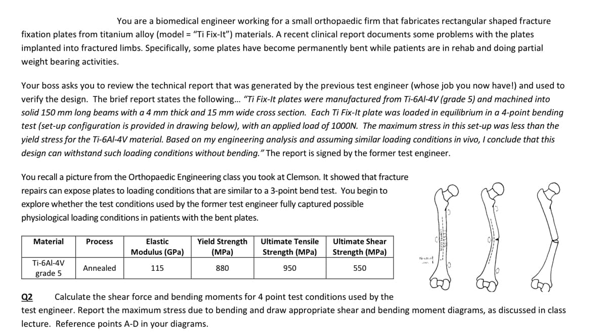
You recall a picture from the Orthopaedic Engineering class you took at Clemson. It showed that fracture
repairs can expose plates to loading conditions that are similar to a 3-point bend test. You begin to
explore whether the test conditions used by the former test engineer fully captured possible
physiological loading conditions in patients with the bent plates.
Material
Ti-6Al-4V
grade 5
Process
Annealed
Elastic
Modulus (GPa)
115
Yield Strength
(MPa)
880
Ultimate Tensile
Strength (MPa)
950
Ultimate Shear
Strength (MPa)
550
III
Neutral
Q2 Calculate the shear force and bending moments for 4 point test conditions used by the
test engineer. Report the maximum stress due to bending and draw appropriate shear and bending moment diagrams, as discussed in class
lecture. Reference points A-D in your diagrams.
Expert Solution
This question has been solved!
Explore an expertly crafted, step-by-step solution for a thorough understanding of key concepts.

Step by step
Solved in 4 steps with 4 images

Knowledge Booster


Learn more about
Need a deep-dive on the concept behind this application? Look no further. Learn more about this topic, mechanical-engineering and related others by exploring similar questions and additional content below.Recommended textbooks for you
Elements Of Electromagnetics
Mechanical Engineering
ISBN:
9780190698614
Author:
Sadiku, Matthew N. O.
Publisher:
Oxford University Press

Mechanics of Materials (10th Edition)
Mechanical Engineering
ISBN:
9780134319650
Author:
Russell C. Hibbeler
Publisher:
PEARSON

Thermodynamics: An Engineering Approach
Mechanical Engineering
ISBN:
9781259822674
Author:
Yunus A. Cengel Dr., Michael A. Boles
Publisher:
McGraw-Hill Education
Elements Of Electromagnetics
Mechanical Engineering
ISBN:
9780190698614
Author:
Sadiku, Matthew N. O.
Publisher:
Oxford University Press
Mechanics of Materials (10th Edition)
Mechanical Engineering
ISBN:
9780134319650
Author:
Russell C. Hibbeler
Publisher:
PEARSON
Thermodynamics: An Engineering Approach
Mechanical Engineering
ISBN:
9781259822674
Author:
Yunus A. Cengel Dr., Michael A. Boles
Publisher:
McGraw-Hill Education

Control Systems Engineering
Mechanical Engineering
ISBN:
9781118170519
Author:
Norman S. Nise
Publisher:
WILEY

Mechanics of Materials (MindTap Course List)
Mechanical Engineering
ISBN:
9781337093347
Author:
Barry J. Goodno, James M. Gere
Publisher:
Cengage Learning

Engineering Mechanics: Statics
Mechanical Engineering
ISBN:
9781118807330
Author:
James L. Meriam, L. G. Kraige, J. N. Bolton
Publisher:
WILEY