
Chapter10: Direct-current Circuits
Section: Chapter Questions
Problem 25P: A 12.0-V emf automobile battery has a terminal voltage of 16.0 V when being charged by a current of...

Related questions
Question
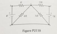
Transcribed Image Text:R
2R
3R
Figure P27.19
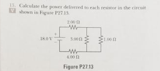
Transcribed Image Text:13. Calculate the power delivered to each resistor in the circuit
V shown in Figure P27.13
2.00 0
18.0 V
3.00n
1.00
4.00 n
Figure P27.13
Expert Solution
This question has been solved!
Explore an expertly crafted, step-by-step solution for a thorough understanding of key concepts.

This is a popular solution!

Trending now
This is a popular solution!

Step by step
Solved in 5 steps with 7 images

Knowledge Booster


Learn more about
Need a deep-dive on the concept behind this application? Look no further. Learn more about this topic, physics and related others by exploring similar questions and additional content below.Recommended textbooks for you