. Find the equivalent impedance of the given circuit. Use 2kHz as frequency.
. Find the equivalent impedance of the given circuit. Use 2kHz as frequency.

Power System Analysis and Design (MindTap Course List)
6th Edition
ISBN:9781305632134
Author:J. Duncan Glover, Thomas Overbye, Mulukutla S. Sarma
Publisher:J. Duncan Glover, Thomas Overbye, Mulukutla S. Sarma
Chapter2: Fundamentals
Section: Chapter Questions
Problem 2.2MCQ: If the rms phasor of a voltage is given by V=12060 volts, then the corresponding v(t) is given by...

Related questions
Question
100%
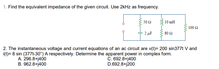
Transcribed Image Text:1. Find the equivalent impedance of the given circuit. Use 2kHz as frequency.
50 2
10 mH
100 2
2 µF
80 2
2. The instantaneous voltage and current equations of an ac circuit are v(t)= 200 sin377t V and
i(t)= 8 sin (377t-30°) A respectively. Determine the apparent power in complex form.
A. 296.8+j400
B. 962.8+j400
C. 692.8+j400
D.692.8+j200
Expert Solution
This question has been solved!
Explore an expertly crafted, step-by-step solution for a thorough understanding of key concepts.

Step by step
Solved in 2 steps

Knowledge Booster


Learn more about
Need a deep-dive on the concept behind this application? Look no further. Learn more about this topic, electrical-engineering and related others by exploring similar questions and additional content below.Recommended textbooks for you
Power System Analysis and Design (MindTap Course …
Electrical Engineering
ISBN:
9781305632134
Author:
J. Duncan Glover, Thomas Overbye, Mulukutla S. Sarma
Publisher:
Cengage Learning
Power System Analysis and Design (MindTap Course …
Electrical Engineering
ISBN:
9781305632134
Author:
J. Duncan Glover, Thomas Overbye, Mulukutla S. Sarma
Publisher:
Cengage Learning