05. If a latching current for the circuit shown in figure is 2 mA. Obtain the value of minimum width of the property turn ON the SCR?
05. If a latching current for the circuit shown in figure is 2 mA. Obtain the value of minimum width of the property turn ON the SCR?

Chapter32: Two-speed, One-winding (consequent Pole) Motor Controllers
Section: Chapter Questions
Problem 6SQ: Describe the operation of Figure 325 (B) by adding jumper wire A to the original circuit.

Related questions
Question
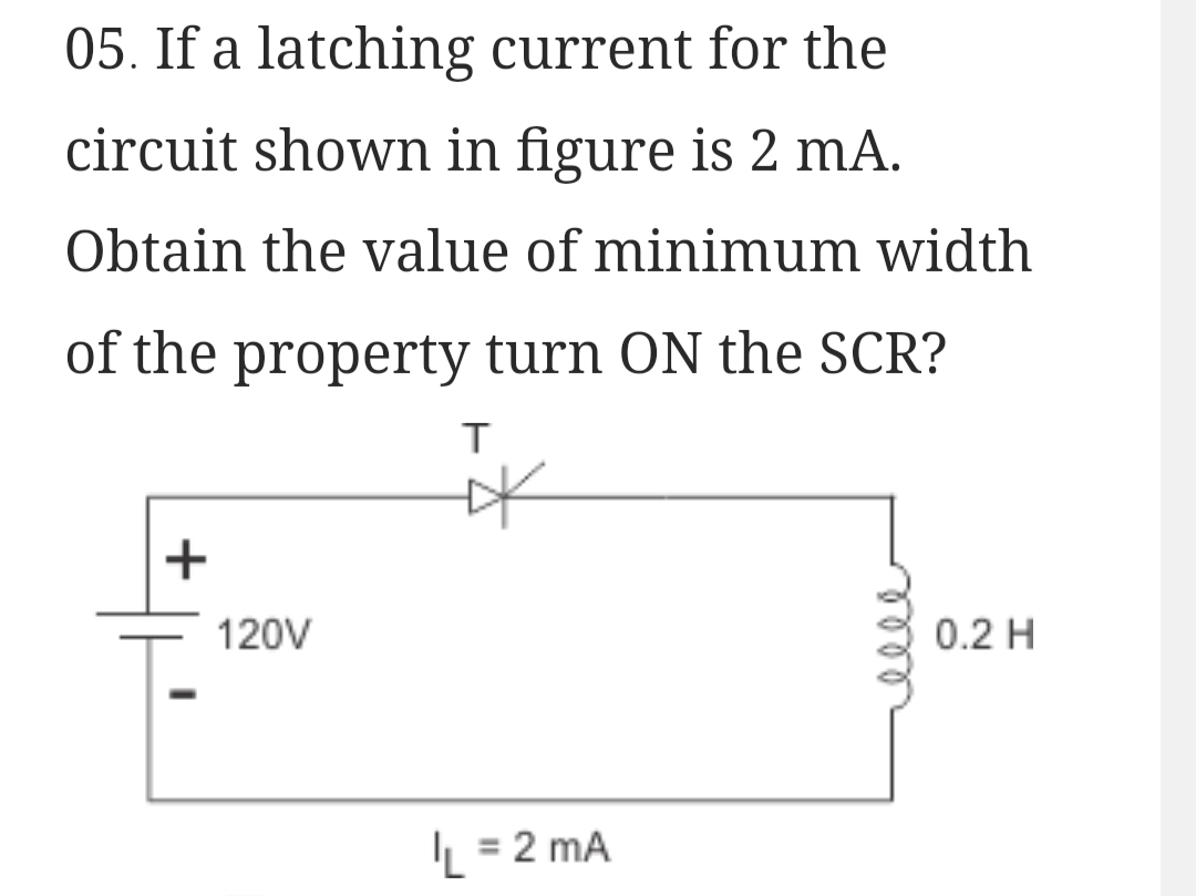
Transcribed Image Text:05. If a latching current for the
circuit shown in figure is 2 mA.
Obtain the value of minimum width
of the property turn ON the SCR?
+
120V
T
*
L = 2 mA
0.2 H
Expert Solution
This question has been solved!
Explore an expertly crafted, step-by-step solution for a thorough understanding of key concepts.

Step by step
Solved in 2 steps with 1 images

Knowledge Booster


Learn more about
Need a deep-dive on the concept behind this application? Look no further. Learn more about this topic, electrical-engineering and related others by exploring similar questions and additional content below.Recommended textbooks for you