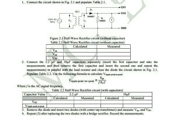
1. Connect the circuit shown in Fig. 2.1 and populate Table 2.1. CH1 D. 18:1 CH2 IN4007 220V AC SOHZ R. 100ka V V. GND Figure 2.1 Half-Wave Rectifier circuit (without capacitor) Table 2.1 Half-Wave Rectifier circuit (without capacitor) Calculated Measured V Ve
1. Connect the circuit shown in Fig. 2.1 and populate Table 2.1. CH1 D. 18:1 CH2 IN4007 220V AC SOHZ R. 100ka V V. GND Figure 2.1 Half-Wave Rectifier circuit (without capacitor) Table 2.1 Half-Wave Rectifier circuit (without capacitor) Calculated Measured V Ve

Introductory Circuit Analysis (13th Edition)
13th Edition
ISBN:9780133923605
Author:Robert L. Boylestad
Publisher:Robert L. Boylestad
Chapter1: Introduction
Section: Chapter Questions
Problem 1P: Visit your local library (at school or home) and describe the extent to which it provides literature...

Related questions
Question
Transcribed Image Text:1. Connect the circuit shown in Fig. 2.1 and populate Table 2.1.
CH1
D.
18:1
- CH2
1N4007
220V AC
SOHE
R.
100k
GND
Figure 2.1 Half-Wave Rectifier circuit (without capacitor)
Table 2.1 Half-Wave Rectifier circuit (without capacitor)
Calculated
Measured
Vap
Vep
Voc
2. Connect the 2.2 uF and 10µF capacitors separately (insert the first capacitor and take the
measurements and then remove the first capacitor and insert the second one and repeat the
measurements) in parallel with the load resistor and close the diode the circuit shown in Fig. 2.1.
Populate Table 2.2. Use the following formula to calculate Veesle pesk-sopek:
Vop
Vripple peak-ta-peak
TRC
Where fis the AC signal frequency.
Table 2.2 Half-Wave Rectifier circuit (with capacitors)
Capacitor Value
2.2 µF
10µF
Measured
Calculated
Measured
Calculated
Vpc
Vripple peak-0-peak
3. Remove the diode and insert two diodes (with center tap transformer) and measure Ve and Vpc.
4. Repeat (3) after replacing the two diodes with a bridge rectifier. Record the measurements.
Expert Solution
This question has been solved!
Explore an expertly crafted, step-by-step solution for a thorough understanding of key concepts.

This is a popular solution!

Trending now
This is a popular solution!

Step by step
Solved in 2 steps

Knowledge Booster


Learn more about
Need a deep-dive on the concept behind this application? Look no further. Learn more about this topic, electrical-engineering and related others by exploring similar questions and additional content below.Recommended textbooks for you
Introductory Circuit Analysis (13th Edition)
Electrical Engineering
ISBN:
9780133923605
Author:
Robert L. Boylestad
Publisher:
PEARSON

Delmar's Standard Textbook Of Electricity
Electrical Engineering
ISBN:
9781337900348
Author:
Stephen L. Herman
Publisher:
Cengage Learning

Programmable Logic Controllers
Electrical Engineering
ISBN:
9780073373843
Author:
Frank D. Petruzella
Publisher:
McGraw-Hill Education
Introductory Circuit Analysis (13th Edition)
Electrical Engineering
ISBN:
9780133923605
Author:
Robert L. Boylestad
Publisher:
PEARSON
Delmar's Standard Textbook Of Electricity
Electrical Engineering
ISBN:
9781337900348
Author:
Stephen L. Herman
Publisher:
Cengage Learning
Programmable Logic Controllers
Electrical Engineering
ISBN:
9780073373843
Author:
Frank D. Petruzella
Publisher:
McGraw-Hill Education

Fundamentals of Electric Circuits
Electrical Engineering
ISBN:
9780078028229
Author:
Charles K Alexander, Matthew Sadiku
Publisher:
McGraw-Hill Education

Electric Circuits. (11th Edition)
Electrical Engineering
ISBN:
9780134746968
Author:
James W. Nilsson, Susan Riedel
Publisher:
PEARSON

Engineering Electromagnetics
Electrical Engineering
ISBN:
9780078028151
Author:
Hayt, William H. (william Hart), Jr, BUCK, John A.
Publisher:
Mcgraw-hill Education,