A single-phase single-pulse diode rectifier (Fig. 3.1), with a resistive load (R=100 0), is fed from an AC voltage sourcev,(1) = Vs-2-sin( ext), where Vs=240 V, f=50 Hz. Fig. 3.1. A single-phase single-pulse diode rectifier with a resistive load a) Calculate the load voltage ripple factor or distortion factor in terms of average and RMS values and explain the result (the value obtained); b) Replace the resistive load with an inductive-resistive one (R-L load), having R=100 0, L=0.06 H. Sketch the load voltage and current waveforms for this case and explain the four distinct regions for each supply period (cycle);
A single-phase single-pulse diode rectifier (Fig. 3.1), with a resistive load (R=100 0), is fed from an AC voltage sourcev,(1) = Vs-2-sin( ext), where Vs=240 V, f=50 Hz. Fig. 3.1. A single-phase single-pulse diode rectifier with a resistive load a) Calculate the load voltage ripple factor or distortion factor in terms of average and RMS values and explain the result (the value obtained); b) Replace the resistive load with an inductive-resistive one (R-L load), having R=100 0, L=0.06 H. Sketch the load voltage and current waveforms for this case and explain the four distinct regions for each supply period (cycle);

Introductory Circuit Analysis (13th Edition)
13th Edition
ISBN:9780133923605
Author:Robert L. Boylestad
Publisher:Robert L. Boylestad
Chapter1: Introduction
Section: Chapter Questions
Problem 1P: Visit your local library (at school or home) and describe the extent to which it provides literature...

Related questions
Question
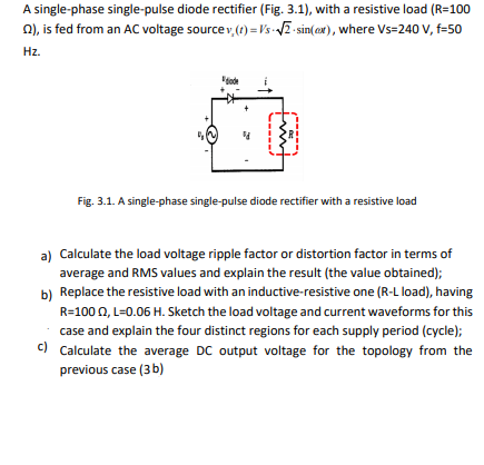
Transcribed Image Text:A single-phase single-pulse diode rectifier (Fig. 3.1), with a resistive load (R=100
n), is fed from an AC voltage sourcev,() = Vs VE sin(ax), where Vs=240 V, f=50
Hz.
Fig. 3.1. A single-phase single-pulse diode rectifier with a resistive load
a) Calculate the load voltage ripple factor or distortion factor in terms of
average and RMS values and explain the result (the value obtained);
b) Replace the resistive load with an inductive-resistive one (R-L load), having
R=100 0, L=0.06 H. Sketch the load voltage and current waveforms for this
case and explain the four distinct regions for each supply period (cycle);
c) Calculate the average DC output voltage for the topology from the
previous case (3 b)
Expert Solution
This question has been solved!
Explore an expertly crafted, step-by-step solution for a thorough understanding of key concepts.

Step by step
Solved in 5 steps with 1 images

Knowledge Booster


Learn more about
Need a deep-dive on the concept behind this application? Look no further. Learn more about this topic, electrical-engineering and related others by exploring similar questions and additional content below.Recommended textbooks for you
Introductory Circuit Analysis (13th Edition)
Electrical Engineering
ISBN:
9780133923605
Author:
Robert L. Boylestad
Publisher:
PEARSON

Delmar's Standard Textbook Of Electricity
Electrical Engineering
ISBN:
9781337900348
Author:
Stephen L. Herman
Publisher:
Cengage Learning

Programmable Logic Controllers
Electrical Engineering
ISBN:
9780073373843
Author:
Frank D. Petruzella
Publisher:
McGraw-Hill Education
Introductory Circuit Analysis (13th Edition)
Electrical Engineering
ISBN:
9780133923605
Author:
Robert L. Boylestad
Publisher:
PEARSON
Delmar's Standard Textbook Of Electricity
Electrical Engineering
ISBN:
9781337900348
Author:
Stephen L. Herman
Publisher:
Cengage Learning
Programmable Logic Controllers
Electrical Engineering
ISBN:
9780073373843
Author:
Frank D. Petruzella
Publisher:
McGraw-Hill Education

Fundamentals of Electric Circuits
Electrical Engineering
ISBN:
9780078028229
Author:
Charles K Alexander, Matthew Sadiku
Publisher:
McGraw-Hill Education

Electric Circuits. (11th Edition)
Electrical Engineering
ISBN:
9780134746968
Author:
James W. Nilsson, Susan Riedel
Publisher:
PEARSON

Engineering Electromagnetics
Electrical Engineering
ISBN:
9780078028151
Author:
Hayt, William H. (william Hart), Jr, BUCK, John A.
Publisher:
Mcgraw-hill Education,