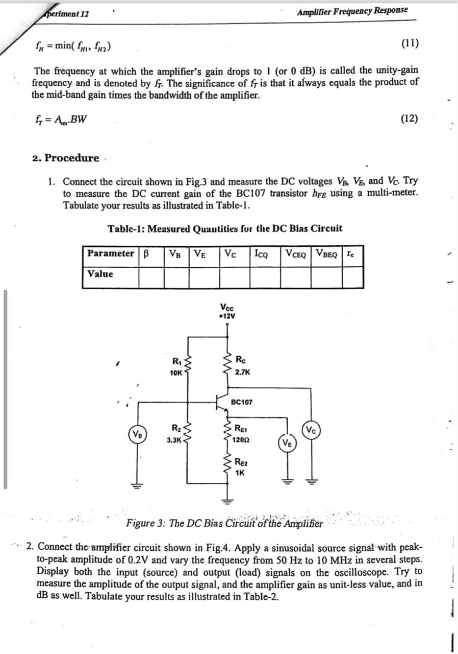
1. Connect the circuit shown in Fig.3 and measure the DC voltages VB, VE, and Vc. Try to measure the DC current gain of the BC107 transistor hfe using a multi-meter. Tabulate your results as illustrated in Table-1. Tablc-1: Measured Quautities fur the DC Bias Circuit Parameter B VB VE Vc IcQ VCEQ VBEQ re Value Vcc +12V Rc R1 2.7K 10K BC107 Vc VE REI (Ve R2 3.3K 1202 RE2 1K Figure 3: The DC Bias Circuit of the Amplifier


Power Amplifier
The power amplifier is an electronic amplifier designed to maximize the signal strength of a given input. The input signal strength is enhanced to a high enough level to drive output devices such as speakers, headphones, RF (Radio frequency) transmitters, etc. Unlike voltage / current amplifiers, the power amplifier is designed to drive core loads directly and is used as a storage block in the amplifier series.
Maximum Efficiency Criterion
In every field of engineering, there is a tremendous use of the machine and all those machines are equipped for their popular work efficiency so it very much important for operation engineers to monitor the efficiency of the machine, planning engineers to check out the efficiency of the machine before installing the machine and design engineers to design machine for higher efficiency than and then the utility will procure their products that will ultimately lead to profit and loss of the company. It indicates the importance of efficiency right from the initial stage as manufacturing units, intermediate stage as planning coordinators, and end-users stage as a utility.

Step by step
Solved in 3 steps with 3 images


