1. Determine the required number of inputs and outputs. 2. Derive the truth table for each of the outputs based on their relationships to the input. 3. Simplify the Boolean expression for each output. Use Karnaugh Maps or Boolean algebra. 4. Draw a logic diagram that represents the simplified Boolean expression.
1. Determine the required number of inputs and outputs. 2. Derive the truth table for each of the outputs based on their relationships to the input. 3. Simplify the Boolean expression for each output. Use Karnaugh Maps or Boolean algebra. 4. Draw a logic diagram that represents the simplified Boolean expression.

Introductory Circuit Analysis (13th Edition)
13th Edition
ISBN:9780133923605
Author:Robert L. Boylestad
Publisher:Robert L. Boylestad
Chapter1: Introduction
Section: Chapter Questions
Problem 1P: Visit your local library (at school or home) and describe the extent to which it provides literature...

Related questions
Question
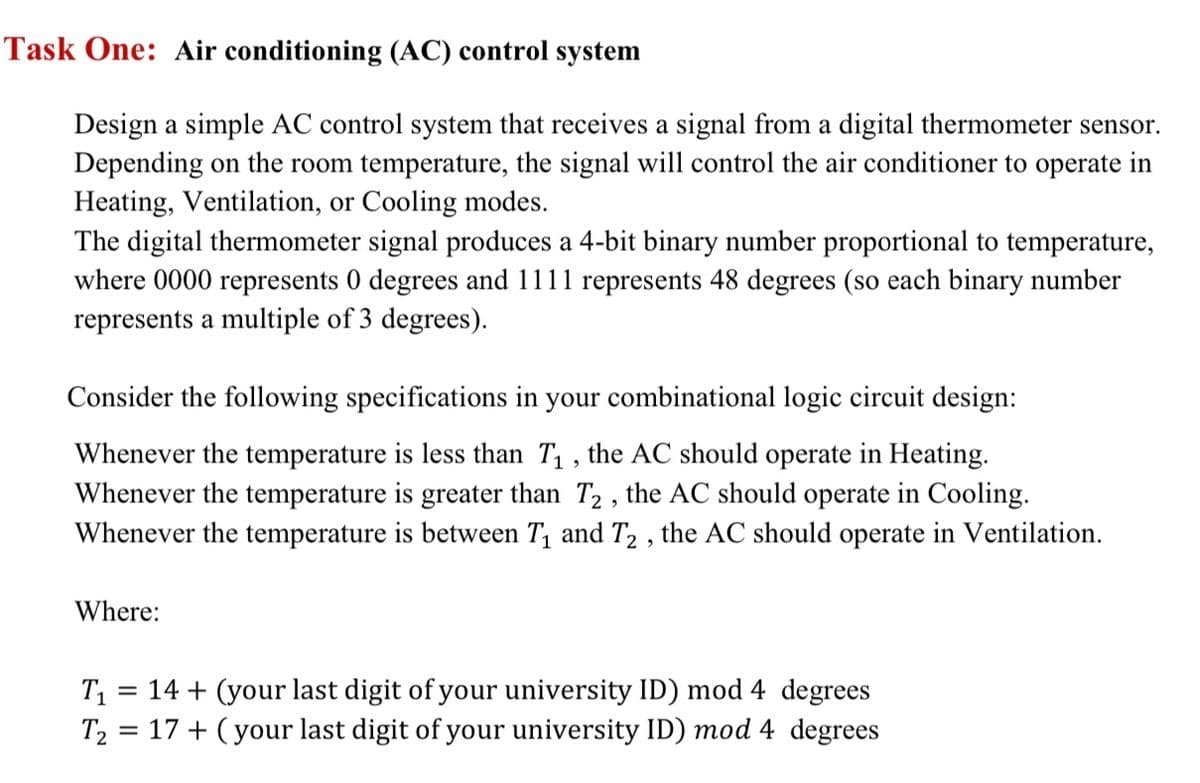
Transcribed Image Text:Task One: Air conditioning (AC) control system
Design a simple AC control system that receives a signal from a digital thermometer sensor.
Depending on the room temperature, the signal will control the air conditioner to operate in
Heating, Ventilation, or Cooling modes.
The digital thermometer signal produces a 4-bit binary number proportional to temperature,
where 0000 represents 0 degrees and 1111 represents 48 degrees (so each binary number
represents a multiple of 3 degrees).
Consider the following specifications in your combinational logic circuit design:
Whenever the temperature is less than T₁, the AC should operate in Heating.
Whenever the temperature is greater than T2, the AC should operate in Cooling.
Whenever the temperature is between T₁ and T2, the AC should operate in Ventilation.
Where:
T₁ = 14 + (your last digit of your university ID) mod 4 degrees
T₂ = 17+ (your last digit of your university ID) mod 4 degrees
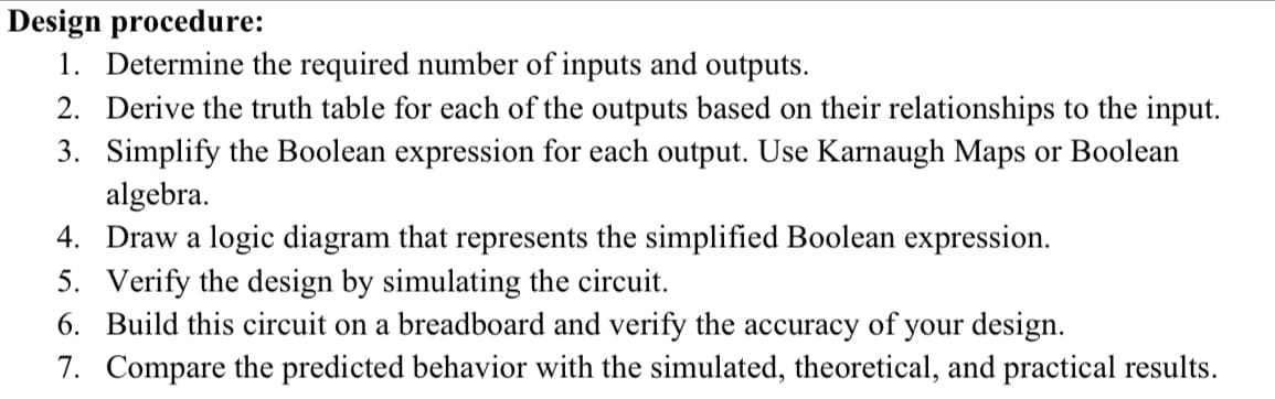
Transcribed Image Text:Design procedure:
1. Determine the required number of inputs and outputs.
2. Derive the truth table for each of the outputs based on their relationships to the input.
3. Simplify the Boolean expression for each output. Use Karnaugh Maps or Boolean
algebra.
4. Draw a logic diagram that represents the simplified Boolean expression.
5.
Verify the design by simulating the circuit.
6. Build this circuit on a breadboard and verify the accuracy of your design.
7. Compare the predicted behavior with the simulated, theoretical, and practical results.
Expert Solution
This question has been solved!
Explore an expertly crafted, step-by-step solution for a thorough understanding of key concepts.

Step by step
Solved in 4 steps with 4 images

Knowledge Booster


Learn more about
Need a deep-dive on the concept behind this application? Look no further. Learn more about this topic, electrical-engineering and related others by exploring similar questions and additional content below.Recommended textbooks for you
Introductory Circuit Analysis (13th Edition)
Electrical Engineering
ISBN:
9780133923605
Author:
Robert L. Boylestad
Publisher:
PEARSON

Delmar's Standard Textbook Of Electricity
Electrical Engineering
ISBN:
9781337900348
Author:
Stephen L. Herman
Publisher:
Cengage Learning

Programmable Logic Controllers
Electrical Engineering
ISBN:
9780073373843
Author:
Frank D. Petruzella
Publisher:
McGraw-Hill Education
Introductory Circuit Analysis (13th Edition)
Electrical Engineering
ISBN:
9780133923605
Author:
Robert L. Boylestad
Publisher:
PEARSON
Delmar's Standard Textbook Of Electricity
Electrical Engineering
ISBN:
9781337900348
Author:
Stephen L. Herman
Publisher:
Cengage Learning
Programmable Logic Controllers
Electrical Engineering
ISBN:
9780073373843
Author:
Frank D. Petruzella
Publisher:
McGraw-Hill Education

Fundamentals of Electric Circuits
Electrical Engineering
ISBN:
9780078028229
Author:
Charles K Alexander, Matthew Sadiku
Publisher:
McGraw-Hill Education

Electric Circuits. (11th Edition)
Electrical Engineering
ISBN:
9780134746968
Author:
James W. Nilsson, Susan Riedel
Publisher:
PEARSON

Engineering Electromagnetics
Electrical Engineering
ISBN:
9780078028151
Author:
Hayt, William H. (william Hart), Jr, BUCK, John A.
Publisher:
Mcgraw-hill Education,