1. Disconnect the previous circuit. On your circuit board, connect your three resistors R, R2 and R3 in parallel, as shown in Fig. 1(b). Do not connect the battery yet! 2. Use one of your multimeters in the ohmmeter mode to measure the resistance of the parallel combination of R,, R2 and R3. Record this as the measured equivalent resistance in Table C on your data sheet. 3. Calculate the theoretical equivalent resistance Reg of this parallel combination of R1, R2 and R3. On separate paper, show your work in calculating this equivalent resistance. Record your theoretical value of Reg in Table C on your data sheet. (See the Theory section for a discussion of how to calculate Reg-) 4. Now use this parallel combination of R,, R2 and R, to construct the parallel circuit shown in Figure 9, with the ammeter in series with the batteries so that it measures the total current / (the current through the batteries). Dov R,= a5 R, = 50n Ra=
1. Disconnect the previous circuit. On your circuit board, connect your three resistors R, R2 and R3 in parallel, as shown in Fig. 1(b). Do not connect the battery yet! 2. Use one of your multimeters in the ohmmeter mode to measure the resistance of the parallel combination of R,, R2 and R3. Record this as the measured equivalent resistance in Table C on your data sheet. 3. Calculate the theoretical equivalent resistance Reg of this parallel combination of R1, R2 and R3. On separate paper, show your work in calculating this equivalent resistance. Record your theoretical value of Reg in Table C on your data sheet. (See the Theory section for a discussion of how to calculate Reg-) 4. Now use this parallel combination of R,, R2 and R, to construct the parallel circuit shown in Figure 9, with the ammeter in series with the batteries so that it measures the total current / (the current through the batteries). Dov R,= a5 R, = 50n Ra=

College Physics
11th Edition
ISBN:9781305952300
Author:Raymond A. Serway, Chris Vuille
Publisher:Raymond A. Serway, Chris Vuille
Chapter1: Units, Trigonometry. And Vectors
Section: Chapter Questions
Problem 1CQ: Estimate the order of magnitude of the length, in meters, of each of the following; (a) a mouse, (b)...

Related questions

Question
How do I solve Table C?
Transcribed Image Text:45
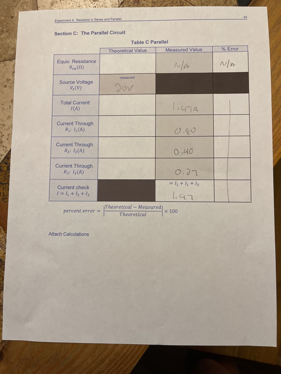
Experiment 4: Resistors in Series and Parallel
Section C: The Parallel Circuit
Table C Parallel
Theoretical Value
Measured Value
% Error
Equiv. Resistance
Reg (2)
N/A
measured
Source Voltage
Vs(V)
2ov
Total Current:
I(A)
Current Through
R1: 14 (A)
0.50
Current Through
R2: I2(A)
0,40
Current Through
R3: 13(A)
0.27
= , + 12 + I3
Current check
I = I, + I2 + I3
l47
|Theoretical - Measured|
percent error =
X 100
Theoretical
Attach Calculations
Transcribed Image Text:Experiment 4 Resstors in Series and Parallel
Experiment 4: Resistors in Series and Parallel
Iculate the theoretical total current I and voltages V,, V, and V.. Record these in Table
Calcu
B on your data sheet. Use the source voltage you measured along with the theoretical
values of the resistances from Table A. Show your work on separate paper! (See the
Theory section, if necessary, for a discussion of the proper way to carry out these
calculations.)
circuits looks like that shown in Figure 10. (You may need to rearrange some of your
connections.)
R-2s Ka-50-ル
7. Calculate the percent errors between your theoretical predictions and your measured
results and record these in Table B on your data sheet.
dou Vs =
Ra
8. According to Kirchhoff's voltage rule, the sum of the voltages V, + V2 + V3 should equal
the source voltage Vs. Compute and record the sum V, + V2 + V3. Compare this to the
theoretical value Vs (that you measured) by computing a percent error.
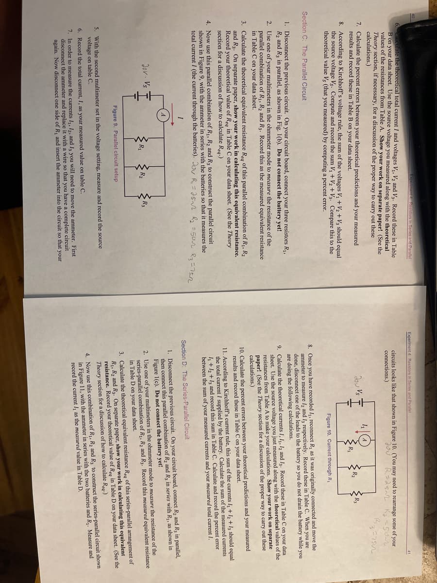
Figure 10. Current through R1
8. Once you have recorded 4, reconnect R, as it was originally connected and move the
ammeter to measure l2 and lz respectively. Record these in Table C. When you are
done, disconnect one of the leads to the battery so you do not drain the battery while you
are doing the following calculations.
Section C: The Parallel Circuit
1. Disconnect the previous circuit. On your circuit board, connect your three resistors R1,
R2 and R3 in parallel, as shown in Fig. 1(b). Do not connect the battery yet!
9. Calculate the theoretical currents I, 1,, 12 and lz. Record these in Table C on your data
sheet. Use the source voltage you just measured along with the theoretical values of the
resistances from Table A to make your calculations. Show your work on separate
paper! (See the Theory section for a discussion of the proper way to carry out these
calculations.)
2. Use one of your multimeters in the ohmmeter mode to measure the resistance of the
parallel combination of R,, R, and R3. Record this as the measured equivalent resistance
in Table C on your data sheet.
3. Calculate the theoretical equivalent resistance Reg of this parallel combination of R1, R2
and R3. On separate paper, show your work in calculating this equivalent resistance.
Record your theoretical value of Reg in Table C on your data sheet. (See the Theory
section for a discussion of how to calculate Rea-)
10. Calculate the percent errors between your theoretical predictions and your measured
results and record these in Table C on your data sheet.
4. Now use this parallel combination of R1, R2 and R3 to construct the parallel circuit
shown in Figure 9, with the ammeter in series with the batteries so that it measures the
total current / (the current through the batteries). Jov R, = a5 R2 =50n Ra=75n
11. According to Kirchhoff's current rule, this sum of the currents l + 12 + l3 should equal
the total current I supplied by the battery. Calculate the sum of the measured currents
I, +12 +13 and record this sum in Table C. Calculate and record the percent error
between the sum of your measured currents and your measured total current I.
Section D: The Series-Parallel Circuit
1. Disconnect the previous circuit. On your circuit board, connect R2 and R3 in parallel,
then connect this parallel combination of R2 and Rg in series with R, as shown in
Figure 1(c). Do not connect the battery yet!
Jor. Vs
2. Use one of your multimeters in the ohmmeter mode to measure the resistance of the
series-parallel combination of R1, R2 and Rg. Record this measured equivalent resistance
in Table D on your data sheet.
R2
R3
3. Calculate the theoretical equivalent resistance Reg of this series-parallel arrangement of
R1, R2 and R3. On separate paper, show your work in calculating this equivalent
resistance. Record your theoretical value of Reg in Table D on your data sheet. (See the
Theory section for a discussion of how to calculate Reg)
Figure 9. Parallel circuit setup
5. With the second multimeter set in the voltage setting, measure and record the source
voltage on table C.
4. Now use this combination of R1, R2 and R3 to construct the series-parallel circuit shown
in Figure 11, with the ammeter in series with the two batteries and R. Measure and
record the current /, as the measured value in Table D.
6. Record the total current, I, as your measured value on table C
7. In order to measure the currents I, 12, and I3 you will need to move the ammeter. First
disconnect the ammeter and replace it with a wire so that you have a complete circuit
again. Now disconnect one side of R, and insert the ammeter into the circuit so that your
Expert Solution
This question has been solved!
Explore an expertly crafted, step-by-step solution for a thorough understanding of key concepts.

This is a popular solution!

Trending now
This is a popular solution!

Step by step
Solved in 3 steps with 3 images

Knowledge Booster


Learn more about
Need a deep-dive on the concept behind this application? Look no further. Learn more about this topic, physics and related others by exploring similar questions and additional content below.Recommended textbooks for you
College Physics
Physics
ISBN:
9781305952300
Author:
Raymond A. Serway, Chris Vuille
Publisher:
Cengage Learning

University Physics (14th Edition)
Physics
ISBN:
9780133969290
Author:
Hugh D. Young, Roger A. Freedman
Publisher:
PEARSON

Introduction To Quantum Mechanics
Physics
ISBN:
9781107189638
Author:
Griffiths, David J., Schroeter, Darrell F.
Publisher:
Cambridge University Press
College Physics
Physics
ISBN:
9781305952300
Author:
Raymond A. Serway, Chris Vuille
Publisher:
Cengage Learning
University Physics (14th Edition)
Physics
ISBN:
9780133969290
Author:
Hugh D. Young, Roger A. Freedman
Publisher:
PEARSON
Introduction To Quantum Mechanics
Physics
ISBN:
9781107189638
Author:
Griffiths, David J., Schroeter, Darrell F.
Publisher:
Cambridge University Press

Physics for Scientists and Engineers
Physics
ISBN:
9781337553278
Author:
Raymond A. Serway, John W. Jewett
Publisher:
Cengage Learning

Lecture- Tutorials for Introductory Astronomy
Physics
ISBN:
9780321820464
Author:
Edward E. Prather, Tim P. Slater, Jeff P. Adams, Gina Brissenden
Publisher:
Addison-Wesley

College Physics: A Strategic Approach (4th Editio…
Physics
ISBN:
9780134609034
Author:
Randall D. Knight (Professor Emeritus), Brian Jones, Stuart Field
Publisher:
PEARSON